





3 Engineering Disciplines Under This Hub
Saline-Alkali Land PV Mounting
Saline-Alkali Land & Salt-Tolerant PV Racking for Improved Wasteland
Coastal Tidal-Flat PV Support
Tidal-Flat & Tidal-Zone PV Brackets for Coastal Intertidal Projects
Salt-Pan & Brine-Pond PV Mounting
Salt-Pan PV Brackets & Brine-Pond Solar Mounting with Floating Options
Why Salinized Land / Tidal Flat projects are demanding
Salinized land and tidal flats put structures in the most corrosive environment short of open sea: brackish groundwater, salt crusts, tidal wet-dry cycles and soft soils. Success is decided by corrosion-class selection, pile detailing below the salt line, and layouts that respect aquaculture or salt-production operations continuing around the arrays.
Site challenges we engineer around:
Challenge 01
Soft saline soils give poor pile lateral capacity; long piles flex under wind
Challenge 02
Tidal windows compress piling schedules into short daily or monthly slots
Challenge 03
Salt crust and spray reach above structure – the splash zone is where systems fail
Challenge 04
Aquaculture and salt operations continue: nets, pumps and harvest paths constrain layout
How to choose the right page
- If the site is inland saline-alkali soil, start with the saline-alkali mounting page
- If tides and soft coastal sediments govern, start with the tidal-flat page
- If the ground is saturated brine, start with the salt-pan page – the corrosion class changes materially
Key technical parameters at a glance
Typical engineering envelopes for this segment; every project is recalculated against the destination-market code before fabrication:
| Parameter | Typical value / approach |
|---|---|
| Foundation options | ground screw, driven pile, rammed pile or ballast selected by soil report |
| Structural design life | 25-year service design with a 10-year structural warranty frame |
| Steel grades | Q235B / Q355B, hot-dip galvanized to ISO 1461, average zinc 85 um or above |
| Design wind | site-specific 3-second gust, typically 33-42 m/s per EN 1991-1-4 or ASCE 7 |
| Corrosion class | duplex coating for chloride and tidal saturation |
| Foundation | high-zinc steel with sealed caps in tidal flats |
Engineering requirements and design basis
- Corrosion class mapping (C4/C5/Im2) with coating system selected per zone, not site-wide
- Long-pile design with lateral capacity verification in soft saline profiles
- Tidal-window installation planning with piling crews and equipment staged accordingly
- Splash-zone detailing: sealed bolt paths, higher zinc mass, duplex systems
What this hub covers
- Corrosion-class selection for saline soil and brine environments
- Soft-ground and tidal-flat foundations with lateral verification
- Salt-pan mounting for saturated and periodically flooded sites
- Coating systems and drainage detailing that extend service intervals

Which configuration fits your site
Three supply configurations cover most salinized land / tidal flat procurement cases:
| Configuration | Structure and finish | Best for | Cost index |
|---|---|---|---|
| Economy line | Q235B main steel, hot-dip galvanized to ISO 1461 | coastal flats near ports | 1.0 (baseline) |
| Standard line | Q355B main members, 85 um+ zinc, pre-assembled brackets | typical salinized land / tidal flat tenders with standard code loads | +15-25% |
| Severe-site line | reinforced sections, duplex coating, sealed hardware | chloride attack and tidal saturation | +35-50% |
Engineered solution
- Tidal-window installation methodology from comparable coastal projects
- Aquaculture-compatible layout service co-designed with pond operations
- Material certificates and coating logs supplied per batch for owner QA
- Maintenance plan with inspection intervals tied to measured corrosion rates
- Corrosion-package supply: duplex coatings, 316-class fasteners where justified, sealed detailing
Industry benchmarks
The reference points below are anonymized industry benchmarks drawn from comparable public projects of this type. They are not claims about projects delivered by us, and no client, developer or operator is identified.
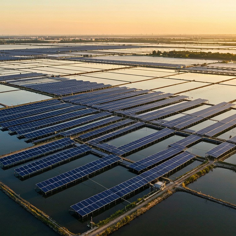
- A 200 MW fishery-PV project in Binzhou, Shandong on coastal saline ponds, with pile rows spaced so harvesting nets keep working. Cited for brackish-water corrosion class and aquaculture-passable layouts.
- A 30 MW mudflat PV plant in Haiyan, Zhejiang, built with piling executed in tidal windows. Reference for tidal-flat access planning and C5-class corrosion protection.
- A 16 MW PV project on salt-pan ponds at Zhangpu, Fujian, on highly corrosive brine soils. Shows the coating and material upgrades required for salt-making ponds.
Installation method and site productivity
Installation method is a cost line, not an afterthought. We ship structures engineered around the equipment you will actually have: pile-driving rigs with template jigs for soils that accept driven piles; screw-pile drives with torque monitoring where refusal or vibration rules out impact; precast ballast pads where penetration is prohibited; and bolt-only table assembly with 80 percent+ shop fabrication so site welding stays at zero. Crew productivity typically runs 40-80 tables per day per rig on prepared corridors, and our installation manual states the assumed crew size, equipment list and daily output so your construction schedule is built on numbers, not optimism.
Standards and compliance
- ISO 12944 C4-C5/Im2 coating selection methodology
- ISO 1461 galvanizing with enhanced zinc mass; duplex systems where specified
- Austenitic or duplex stainless fasteners in splash zones
- IEC 62738 and coastal structural codes as applicable
- ISO 9001 production quality management; batch traceability
- CE / EN 1090 documentation where destination markets require
Budget drivers and lead time
- Corrosion packages add 8-15 percent; they are cheaper than first repaint at year 5
- Long piles in soft saline soils are a discrete cost line – confirm with borings plus pull-out tests
- Tidal logistics can add 5-10 percent to installation if not planned
- Lead time: 8-12 weeks including corrosion packages; batch certificates included
- Quotations state steel grade, zinc mass and coating system explicitly; Incoterms and container plans are quoted to your destination port
Comparing supplier quotations
The cheapest structure per tonne is rarely the cheapest per megawatt installed. Compare at installed-cost level: pile count and driving productivity on your soils; preassembly ratio and site welding (should be zero); crane and crew days implied by the table design; tolerance adjustment range – wider ranges absorb terrain error and cut rework; packaging density and container count; and the commissioning support included. Then compare at ten-year level: coating life to first maintenance, fastener replacement expectations, spare parts availability commitments, and whether warranty claims reference measurable criteria. We quote with these lines visible so your finance team sees the same picture your engineers do.
Frequently asked questions
How much does salt exposure change the specification?
What is the first thing that fails in salt environments?
Can the service life be predicted?
Who owns the structural design – can we modify it?
How are change orders handled during production?
Ready to Start Your Salinized land / tidal flat Project?
What to include in your RFQ
- Soil resistivity and chloride content where available
- Tidal range or inundation frequency for coastal and salt-pan sites
- Target service life and first-maintenance expectation
- Any restrictions on ground penetration or drainage
From RFQ to commissioning: how we work
Procurement runs smoother when both sides know the sequence. Our standard flow: RFQ received – acknowledged within one working day with a list of anything missing (geotech data, design wind speed, module model, terrain category); engineering review – typically three to five working days; quotation – itemized, with steel grade, zinc mass, coating system and Incoterms explicit; sample or pilot lot – available for new partners who want to verify fit and finish before volume; production and inspection – your QC team or a third party is welcome at pre-shipment; shipping – container optimization against your unloading equipment; installation – manuals, videos and a named contact through commissioning. The flow is boring on purpose: fewer surprises, faster approvals.
Send your soil and water data – we will specify the corrosion class and coating system your site actually needs.
Quality, warranty and delivery
Production follows ISO 9001 procedures with batch traceability from coil to container; galvanizing runs to ISO 1461 with zinc mass selected by your site corrosivity class. We publish our first-maintenance estimates in writing, and our warranty documentation names what is covered, for how long, and under which load cases.
Control points from intake to handover
| Stage | What is checked | You receive |
|---|---|---|
| Material intake | steel grade and zinc mass verified against mill certificates | mill certificates and intake report |
| Production | weld quality, hole positioning and coating thickness sampled per batch | batch traceability sheet and QC photos |
| Pre-shipment | container loading plan, bolt-kit counts and packing list reviewed | packing list and loading photos |
| Site handover | installation walkthrough with torque values confirmed | installation manual, torque table and warranty letter |
| Site-specific check | duplex coating thickness audit per salt-spray class | project-specific method statement |
Documentation you receive
Buyers comparing suppliers should compare document depth, because claims are easy and records are not. We provide: design basis documents that name standards, load cases and safety factors explicitly; batch-level quality records (steel, galvanizing, fasteners) retained for the warranty period; installation and maintenance manuals written for site crews, not marketing; warranty terms that specify what is covered, for how long, and the claim process; and end-of-project dossiers suitable for handover to your O&M contractor. For multi-project buyers we keep a document history per site, so year-eight extensions reference year-one assumptions instead of starting from zero.
Service life and maintenance planning
Plan maintenance around measurable triggers, not calendar guesses. Annual visual inspection of fastener torque samples, coating condition at cut edges and ground-contact zones; a detailed inspection after the first extreme weather year – typhoon, sandstorm or heavy snow depending on your region; re-torque verification after the first thermal cycle on long tracker runs. We supply the inspection checklist and acceptance criteria with the installation manual, so your O&M team measures against the same numbers our factory used. Where structures sit in aggressive soils or salt zones we advise higher zinc mass and drainage detailing up front – cheaper than retrofits.
