





Why This Is Difficult
The constraints are structural, legal and practical at the same time, and they interact. A fixing method that satisfies the structure may void the roof warranty; a ballast layout that protects the warranty may exceed the purlin capacity; and either may block the only maintenance route across the roof.
- Roof structural reserve is usually unknown, because the building was designed decades ago and the drawings rarely match what was built
- Uplift at parapets and corners can be two to three times the field value, and ballast placed uniformly is either wasteful or unsafe
- Roof membranes are warrantied against penetration unless the fixings are installed by an approved contractor, which pushes projects toward heavier ballast
- Fragmented roofs produce many small array blocks, each needing its own DC isolation, maintenance access and fire setback
- Access logistics – hatch size, lift capacity, no crane on the roof – constrain both the components that can be used and the speed of installation
Engineering Requirements
These are the inputs and detailing decisions we require before a commercial rooftop design is frozen.
- As-built roof survey covering purlin type and spacing, deck condition and any existing penetrations or previous works
- Structural verification of the array dead load plus ballast against available roof reserve, zone by zone
- Uplift zoning per ASCE 7 or EN 1991 with ballast or fixing density stepped by roof zone rather than applied uniformly
- Written compatibility statement for the roof membrane system, stating which fixing method is approved and who holds the warranty afterwards
- Fire and code compliance: setback from parapets and party walls, smoke vent clearance and rapid shutdown provisions
- Maintenance access plan with walkway routes, fall protection and clearances for skylights and plant access
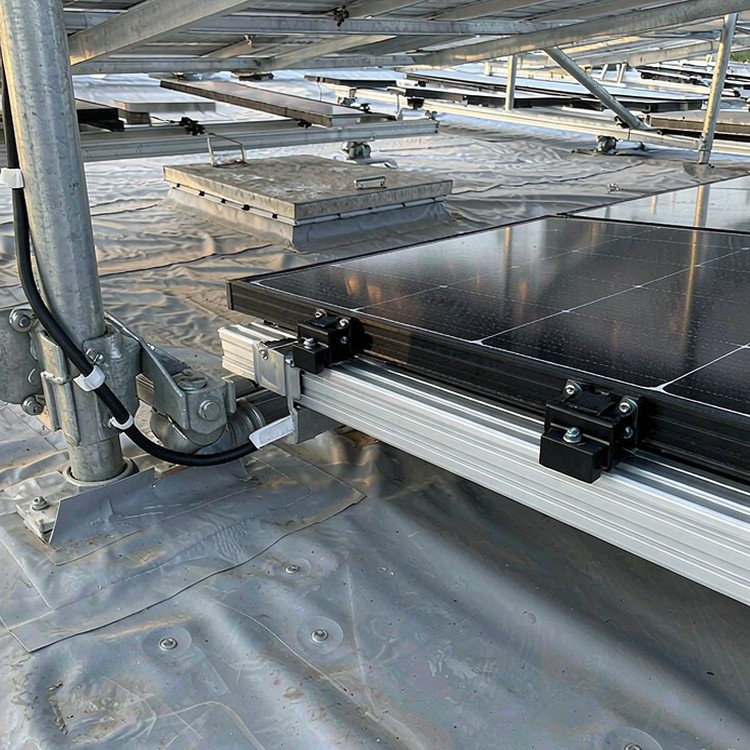
Selection guidance: decide ballast versus penetration first. That single decision sets the load case, the warranty path and the installation method, and changing it later invalidates all three.
How We Solve It
- Zone-stepped ballast design calculated per roof zone, so perimeter and corner areas receive the uplift they actually need and the field does not carry unnecessary load
- Load-spreading pads and rail geometry that distribute ballast onto the deck ribs rather than crushing the panel or the insulation
- Non-penetrating systems for membrane roofs, and engineered sealing details where penetration is approved by the roof system manufacturer
- Pre-assembled rail and clamp kits sized to pass through the building’s actual access hatch and lift rather than to a theoretical dimension
- Layout optimisation that maintains clear bands around skylights, vents and access routes without stranding usable roof area
- DC isolation and array blocking aligned to maintenance routes, so fault-finding does not require walking the whole roof
Beyond the Structure
- Roof block layouts issued as a set, so installation crews can work building-by-building without re-reading the whole drawing package
- Downtake and cable route coordination with the building’s existing services, avoiding both new penetrations and clashes
Reference Benchmarks
Benchmarks below are publicly documented industry reference projects of comparable type and scale, cited to illustrate engineering practice. They are not our delivery record.
- A 1.2 MW rooftop array across two logistics halls in southern Germany, ballasted on a membrane roof with zero penetrations to preserve a 20-year roofing warranty.
- An 800 kW installation on an automotive components plant in Thailand, using penetrating feet on a trapezoidal metal deck where the roof warranty permitted engineered fixings.
- A 2.5 MW C&I portfolio in Spain split across seven distribution centres, standardised on one rail and clamp family so maintenance crews needed a single spares kit.
Standards and Compliance
- ASCE 7 / EN 1991 wind loads resolved with site-specific terrain and exposure factors
- IEC 61215 / IEC 61730 module interface compatibility verified against your module datasheet
- EN 1090 or AISC execution classes for welded and bolted steelwork
- Hot-dip galvanizing to ISO 1461, zinc mass specified by soil and atmospheric corrosivity
- ISO 9001 production quality management with batch-level traceability
- CE / EN 1090 documentation pack where destination markets require it
Quality Assurance
Batch documentation is issued per lot: mill certificates traceable to heat numbers, galvanizing records with measured coating thickness, dimensional inspection reports from pre-assembly jigs and hardware lot traceability. Warranty covers named load cases and environmental exposure classes, so claims are settled against data rather than negotiation.
Documentation You Receive
Each shipment carries a document pack aligned to your asset register: certified material test reports, coating thickness records per batch, torque and preload verification sheets, packing lists with container numbers and a maintenance-relevant drawing set. Where the destination market requires local certification or translated documents, we prepare them in advance rather than at the port.
Service Life and Maintenance Planning
Service life is a design output, not a promise. Zinc mass, fastener coating class, drainage detailing and dissimilar-metal isolation are selected against the corrosivity category of your site, and the expected first-maintenance interval is stated in writing. For aggressive environments we step the coating system up at design stage, which is always cheaper than a retrofit.
Cost and Commercial Considerations
- Ballast typically runs 15-25 percent above equivalent penetrating racking once load-spreading material is included
- Roof structural strengthening, where required, is the largest single swing item and is usually discovered late if the survey is skipped
- Access constraints such as hatch size, lift capacity and no crane on the roof can add 10-20 percent to installation labour
- Cable management, walkways and fall protection are frequently omitted from first bids and added at contract stage
- Lead time: 3-6 weeks for standard rail kits, 6-10 weeks where engineered sealing details or ballast trays are project-specific
Frequently Asked Questions
Do we need to strengthen the roof before installing a commercial array?
Can you install on a roof with a strict membrane warranty?
How do you handle roofs fragmented by skylights and plant?
What load budget should we plan for on a ballasted roof?
Can you supply across a multi-site C&I portfolio?
Related Guides and Application Pages
Continue with the pages closest to your project type.
What We Need to Quote
- As-built roof drawings or a measured survey showing purlin spacing and deck type
- Design wind speed, building height, terrain category and any snow load case
- Roof system manufacturer and membrane warranty terms, including any penetration restrictions
- Target capacity per roof block and the module model to be used
Talk to a Structure Engineer
Send your roof survey and layout, and we will return a ballast plan, an uplift zone map and a costed supply package for the building.
