




Why This Is Difficult
Screws are usually selected for reasons other than cost, and the reason in each case changes the specification.
- Refusal in dense or rocky strata stops driven piles but does not stop a screw, which can be advanced with controlled torque
- Vibration-sensitive ground near pipelines, buildings, instrumentation or landfill caps rules out impact driving and often vibratory driving as well
- Sites with a decommissioning obligation need foundations that can be fully removed and the ground reinstated
- Installation torque gives a capacity indication on every pile rather than on a tested sample, which changes the verification economics
- Screw piles tolerate a wider range of soil conditions within one site, reducing the cost penalty of variable ground
- In deep frost zones the screw can be designed to bear below the frost line without the driving stresses a long driven pile would carry
Engineering Requirements
These are the decisions that define a ground screw specification.
- Soil profile with corrosivity testing, since both helix diameter selection and coating class depend on it
- Design loads per foundation with the governing uplift and compression cases stated separately
- Installation torque target correlated to capacity, established from a site test programme rather than assumed from tables
- Helix geometry: number of helices, diameter and spacing, selected against soil type and required capacity
- Coating system for buried steel, with corrosion allowance or sacrificial thickness defined for the site soil class
- Equipment access and reinstatement plan, particularly where vegetation, surface finish or capped ground must be preserved
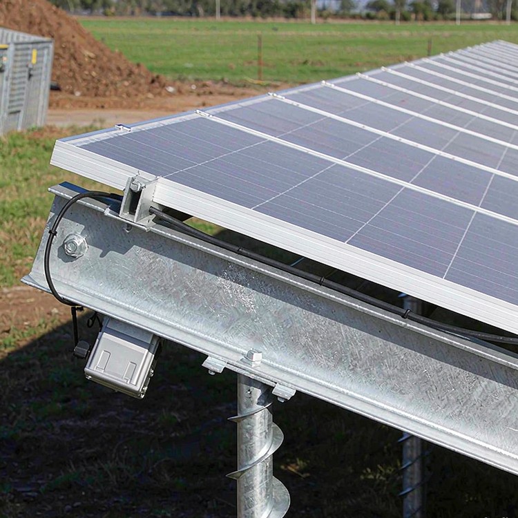
Selection guidance: correlate installation torque to capacity with a site test. Torque correlation is what makes screw piles verifiable, and a correlation assumed from a table rather than measured is not verification.
How We Solve It
- Helix geometry selected against the site soil type, with capacity delivered by bearing on the helix rather than by shaft friction alone
- Torque-correlated installation, so every foundation carries an installation record that indicates its capacity
- Corrosion allowance and coating system specified by soil class, with the buried section treated separately from the above-ground structure
- Installation with compact equipment where access or surface protection demands it, without a piling rig
- Reversible design: foundations can be extracted at decommissioning and the ground reinstated to meet restoration obligations
- Extension shafts for deeper frost penetration or for bringing the connection above finished grade without changing the foundation
Beyond the Structure
- Ground disturbance limited to the screw footprint, preserving surface vegetation, drainage and any capping layer
- Installation records per foundation issued as part of the as-built set, supporting both warranty and future capacity assessment
Reference Benchmarks
Benchmarks below are publicly documented industry reference projects of comparable type and scale, cited to illustrate engineering practice. They are not our delivery record.
- A 40 MW landfill project in Italy using ground screws to avoid penetrating the cap, with foundations extracted and the surface reinstated at end of life.
- A 60 MW project in Japan where vibration limits near existing infrastructure ruled out driving, and torque-correlated screws provided per-foundation capacity records.
- A 25 MW community solar programme in the United States on shallow bedrock, where screws removed the refusal problem that had stopped a driven pile design.
Standards and Compliance
- ASCE 7 / EN 1991 wind loads resolved with site-specific terrain and exposure factors
- IEC 61215 / IEC 61730 module interface compatibility verified against your module datasheet
- EN 1090 or AISC execution classes for welded and bolted steelwork
- Hot-dip galvanizing to ISO 1461, zinc mass specified by soil and atmospheric corrosivity
- ISO 9001 production quality management with batch-level traceability
- CE / EN 1090 documentation pack where destination markets require it
Quality Assurance
Quality control is checkpoint-based: material intake verification, in-process weld and hole-position inspection, coating thickness sampling and pre-shipment container review. Each checkpoint produces a document your quality team can file, and pre-shipment inspection is open to your inspector or a third party.
Documentation You Receive
The paper trail matters as much as the steel. With each delivery you receive mill test certificates traceable to heat numbers; galvanizing records per batch against ISO 1461 or your specified standard; dimensional inspection reports from pre-assembly jigs; bolt and hardware lot traceability; as-built drawings where site adaptations were made; and a warranty document naming covered load cases, service design life and claim procedures. Everything is indexed, so your asset register does not depend on one engineer’s memory.
Service Life and Maintenance Planning
Service life is a design output, not a promise. Zinc mass, fastener coating class, drainage detailing and dissimilar-metal isolation are selected against the corrosivity category of your site, and the expected first-maintenance interval is stated in writing. For aggressive environments we step the coating system up at design stage, which is always cheaper than a retrofit.
Cost and Commercial Considerations
- Ground screws typically cost more per foundation than driven piles, with the gap driven by helix size, coating class and shaft length
- Installation speed is usually lower than driven piles in favourable soils, but higher where refusal would otherwise have stopped the rig
- Torque-correlated installation reduces verification cost, because per-foundation records replace an extensive separate test programme
- Reinstatement value is a real line item on leased or capped land, where extraction and surface restoration may be contractually required
- Lead time: 4-8 weeks for standard screw families, longer where a high hot-dip coating class or stainless components are specified
Frequently Asked Questions
When do ground screws make more sense than driven piles?
How is capacity verified for a screw pile?
What about corrosion of buried steel?
Can screws be installed without heavy equipment?
Can they be removed and reused?
Related Guides and Application Pages
Continue with the pages closest to your project type.
What We Need to Quote
- Soil investigation data with resistivity and chemical test results for corrosivity class
- Design load per foundation, with governing uplift and compression cases stated separately
- Whether extraction or reinstatement is required at end of life
- Access constraints and the equipment you expect to use for installation
Talk to a Structure Engineer
Send the soil investigation and load case, and we will return a helix configuration, a torque target and a coating specification with the installation record structure the project will need.
