





Why This Is Difficult
Driven piles fail in a small number of recognisable ways, and each one traces back to a decision taken before installation started.
- Soil profiles vary across a site far more than a single borehole suggests, so refusal can appear in one zone while adjacent zones drive freely
- Over-driving damages the pile head or the coating, and the damage is usually invisible until the structure is loaded
- Pile position and plumb tolerance determine whether the structure assembles without rework, because racking adjustment ranges are finite
- Pull-out and lateral capacity depend on soil friction, which changes with moisture content and cannot be verified after driving
- Coating damage at the ground line is the most common long-term durability failure on driven piles and the hardest to inspect
- Driving productivity sets the construction programme, so pile refusal is a schedule event rather than a technical inconvenience
Engineering Requirements
These are the inputs that decide driven pile section, depth and method.
- Geotechnical investigation with boreholes or cone penetration tests at a density reflecting the site’s variability, not a single central hole
- Soil classification and corrosivity testing, since both the design embedment and the coating class depend on them
- Design uplift, compression and lateral loads per pile, derived from the structural load case and foundation layout
- Pile section, wall thickness and steel grade selected against both design load and the driving stresses the method will impose
- Driving method and equipment: impact or vibratory, hammer energy, and the refusal criterion to be applied
- Verification protocol: static or dynamic load testing sample rate, and acceptance criteria for production piles
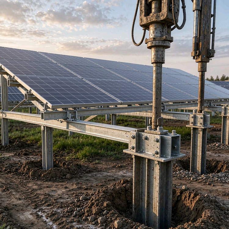
Selection guidance: fix the pile section from the geotechnical data and then choose the driving method to suit the soil. Choosing equipment first and designing the pile to survive it is how coating damage and refusal enter a project.
How We Solve It
- Pile sections selected against both design load and driving stress, so the pile that carries the load also survives installation
- Embedment depth derived from site soil friction and bearing values, with zone-by-zone depths where the profile changes
- Driving method matched to the soil: impact for dense strata, vibratory where displacement is acceptable and speed matters
- Coating specification stepped by soil corrosivity, with additional protection at the ground line where abrasion concentrates
- Tolerance control through template jigs and position surveying, keeping pile heads inside the structure adjustment envelope
- Verification by testing a defined sample, with production acceptance criteria tied to logged driving records
Beyond the Structure
- Driving records logged per pile, so refusal zones and over-driving are visible during installation rather than discovered at commissioning
- Pile head detailing that accommodates re-levelling after settlement, avoiding foundation rework in the first operating years
Reference Benchmarks
Benchmarks below are publicly documented industry reference projects of comparable type and scale, cited to illustrate engineering practice. They are not our delivery record.
- A 300 MW project in Chile where vibratory driving was selected after impact driving produced coating damage in the upper soil layer.
- A 180 MW site in Spain with variable calcarenite bands, where zone-specific embedment depths avoided a refusal problem that a single uniform depth would have created.
- A 250 MW project in the United States using dynamic load testing on a defined sample, replacing a larger static test programme without changing the design basis.
Standards and Compliance
- ASCE 7 / EN 1991 wind and EN 1998 / IBC seismic load combinations where applicable
- IEC 61215 module mechanical load test levels matched to your array design pressure
- EN 1090-1/-2 or AISC execution classes for structural steel components
- ISO 1461 galvanizing with zinc mass stepped by corrosivity category C2 to C5
- ISO 9001:2015 quality management and documented supplier qualification
- DNV or equivalent bankability review support for financed projects
Quality Assurance
Batch documentation is issued per lot: mill certificates traceable to heat numbers, galvanizing records with measured coating thickness, dimensional inspection reports from pre-assembly jigs and hardware lot traceability. Warranty covers named load cases and environmental exposure classes, so claims are settled against data rather than negotiation.
Documentation You Receive
Each shipment carries a document pack aligned to your asset register: certified material test reports, coating thickness records per batch, torque and preload verification sheets, packing lists with container numbers and a maintenance-relevant drawing set. Where the destination market requires local certification or translated documents, we prepare them in advance rather than at the port.
Service Life and Maintenance Planning
Plan maintenance around measurable triggers, not calendar guesses: annual visual inspection of fastener torque samples, coating condition at cut edges and ground-contact zones; a detailed inspection after the first extreme weather year; and re-torque verification after the first thermal cycle on long runs. We supply the inspection checklist and acceptance criteria with the installation manual.
Cost and Commercial Considerations
- Pile steel is quoted per tonne, but the number that governs project cost is piles per day, which is a function of the soil rather than of the price
- Under-investing in geotechnical investigation is the most expensive saving on a driven pile project, because it converts a design problem into a construction problem
- Coating upgrades at the ground line are a small unit cost with a large effect on year-ten maintenance
- Dynamic load testing is substantially cheaper per pile than static testing and can be applied at higher sample rates for the same budget
- Refusal and re-driving are schedule costs, and a single day of pile rig downtime on a 200 MW site is material against the energisation date
Frequently Asked Questions
How do you decide embedment depth?
Impact or vibratory driving?
How do we know the piles will hold?
What pile position tolerance can the structure accept?
Does pile driving damage the coating?
Related Guides and Application Pages
Continue with the pages closest to your project type.
What We Need to Quote
- Geotechnical investigation report including borehole logs, soil classification and corrosivity results
- Design uplift, compression and lateral load per pile, with the foundation layout
- Pile section, length and coating class currently assumed, if already defined
- Available driving equipment and any site access constraints that limit rig size
Talk to a Structure Engineer
Send the geotechnical report and the foundation layout, and we will return a pile section recommendation, zone-by-zone embedment depths and a verification protocol sized to your site.
