
Warum das schwierig ist
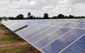
Terrain affects trackers through geometry, and the mechanisms are specific.
- Row straightness is a mechanical requirement, because a torque tube has limited ability to absorb vertical and angular misalignment between foundations
- Slope across a row translates directly into foundation length variation, changing the foundation cost per megawatt and the design of the pile heads
- North-south slope tolerance is generally more generous than east-west, because the tracker rotates about a north-south axis
- Backtracking configuration changes both the shading model and the land requirement, and the optimum differs between flat and sloping ground
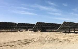
- Undulating ground creates local high and low points that determine the deepest foundation on a row, and the whole row is designed for the worst case
- Steep terrain reduces installable density and increases civil works, both of which erode the tracker economic advantage
Technische Anforderungen
These are the site data and design decisions that determine terrain feasibility.
- Topographic survey at a resolution that captures the undulation that matters for row alignment, not a coarse site-wide surface
- Permissible slope limits for the tracker in both directions, stated by the manufacturer rather than inferred
- Foundation length range required across the site, with the deepest and shortest cases identified per row
- Backtracking algorithm and its configuration, including whether terrain-following or fixed backtracking is used
- Civil works scope: cut and fill volumes, grading tolerance and any terrace provision required to make rows workable
- Installable density calculation that reflects the terrain-adjusted layout rather than the flat-ground layout
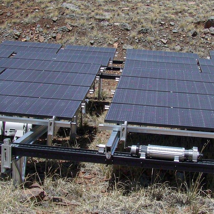
Selection guidance: run the layout on the actual surveyed surface before committing to tracking. A tracker layout developed on a flat plane and applied to a sloping site produces both a cost surprise and a yield shortfall.
Wie wir es lösen
- Layout development on the surveyed surface, so row positions reflect actual ground rather than an idealised plane
- Foundation length variation reported per row, with the deepest case identified so each row is designed against its real governing condition
- Backtracking configured for the site terrain, since the algorithm that suits flat ground is not automatically the right one on a slope
- Slope-aware row direction selection, exploiting the more generous north-south tolerance where the site allows
- Civil works scoped against a defined grading tolerance, so earthworks cost is visible in the comparison rather than discovered during construction
- Installable density calculated from the terrain-adjusted layout, keeping the yield model honest about how much capacity the site actually accepts
Jenseits der Struktur
- Hybrid deployment where terrain exceeds the tracker practical limits, capturing the gain on the workable portion of the site
- Early terrain feasibility screening, so a site is screened out before significant design effort is spent on a layout it cannot support
Referenz-Benchmarks
Die folgenden Benchmarks sind öffentlich dokumentierte Branchenreferenzprojekte vergleichbarer Art und Größenordnung, die zur Veranschaulichung der Ingenieurpraxis dienen. Sie stellen nicht unsere Leistungsbilanz dar.
- A 200 MW project in Chile on undulating ground where foundation length variation across rows was mapped before design, avoiding over-budget foundation quantities.
- A 150 MW site in Spain where east-west slope forced a terrace solution, and the civil works cost was compared against a fixed-tilt alternative before award.
- A 120 MW project in India where terrain-following backtracking improved production on a north-south slope compared with a fixed backtracking configuration.
Standards und Konformität
- ASCE 7 / EN 1991 Windlastkombinationen und EN 1998 / IBC Erdbebenlastkombinationen, sofern anwendbar
- Die mechanischen Belastungstestpegel gemäß IEC 61215 sind auf den Auslegungsdruck Ihres Arrays abgestimmt.
- Ausführungsklassen nach EN 1090-1/-2 oder AISC für Bauteile aus Stahl
- ISO 1461 Verzinken mit Zinkmasse, gestaffelt nach Korrosivitätskategorie C2 bis C5
- Qualitätsmanagement nach ISO 9001:2015 und dokumentierte Lieferantenqualifizierung
- Unterstützung durch DNV oder eine gleichwertige Bankfähigkeitsprüfung für finanzierte Projekte
Qualitätssicherung
Jede Charge wird mit Werkszeugnissen, Schichtdickenprotokollen und Schraubenprotokollen ausgeliefert; die Schweißnähte entsprechen den Ausführungsklassen EN 1090 oder AISC. Die Gewährleistung auf die Struktur beträgt 10 Jahre bei einer geplanten Nutzungsdauer von 25–30 Jahren. Die Ersatzteilpakete sind so dokumentiert, dass Reparaturen im 12. Jahr nicht auf den Daten des ersten Jahres basieren.
Dokumentation, die Sie erhalten
Die Dokumentation dient Prüfungszwecken, nicht der Dekoration: Statische Berechnungshinweise mit Angabe der Lastfälle und verwendeten Normen; Fundamentberechnungsgrundlagen, die auf Ihren geotechnischen Bericht abgestimmt sind; Materialzertifikate für Stahl und Befestigungsmittel; Verzinkungszertifikate mit Angabe der Schichtdicke pro Charge; Montagezeichnungen mit Drehmomenttabellen; und Verpackungsdokumentation, die mit den Containermanifesten übereinstimmt. Bei finanzierten Projekten ergänzen wir die Dokumentation um Konformitätserklärungen im Format des Kreditgebers; bei öffentlichen Ausschreibungen erfüllen wir die Dokumentationsvorgaben Zeile für Zeile.
Lebensdauer- und Wartungsplanung
Die Wartung sollte anhand messbarer Kriterien und nicht anhand von Schätzungen im Kalender erfolgen: jährliche Sichtprüfung der Anzugsmomente von Befestigungselementen, Zustand der Beschichtung an Schnittkanten und Erdungskontaktstellen; eine detaillierte Prüfung nach dem ersten Jahr mit extremen Witterungsbedingungen; und Überprüfung des Anzugsmoments nach dem ersten Temperaturzyklus bei langen Strecken. Die Prüfcheckliste und die Abnahmekriterien stellen wir zusammen mit der Installationsanleitung zur Verfügung.
Kosten- und kommerzielle Überlegungen
- Foundation length variation is the most direct terrain cost, since the deepest foundation on a row governs that row design, so local ground features raise cost disproportionately
- Civil works to achieve grading tolerance can be substantial and must be compared against the yield the tracker will produce on the adjusted layout
- Installable density loss on steep or irregular ground reduces the capacity a given land area supports, which changes the economics rather than just the layout
- Survey cost at the resolution required is modest and prevents the largest category of layout error
- Beyond a certain slope the tracker cannot be adapted economically, and the decision becomes fixed-tilt on the difficult portion rather than more earthworks
Häufig gestellte Fragen
How steep a slope can a tracker handle?
What is backtracking and why does terrain change it?
When does terrain rule out tracking?
How accurate a survey is needed?
Does terrain affect the yield model?
Verwandte Leitfäden und Anwendungsseiten
Fahren Sie mit den Seiten fort, die Ihrem Projekttyp am ehesten entsprechen.
- Wirtschaftlichkeit von Tracker- gegenüber Fixed-Title-Konten – die Gruppenübersicht für dieses Skalenband
- Wirtschaftlichkeit von einachsigen Trackern für Energieversorgungsprojekte
- Festneigbare vs. nachgeführte Teleskope: Ertrags- und Kostenvergleich
- Tracker-Anwendungen: Komplexes Gelände und hügelige Standorte
- Anwendungen von Tracker-Systemen
- Solarenergieprojekte an Hängen und sanften Hängen
Was wir für ein Angebot benötigen
- Topographic survey data for the developable area
- Tracker model and its published slope and row-alignment tolerances
- Intended backtracking configuration, or a request for a recommendation
- Earthworks assumptions or constraints, including any restrictions on grading
Sprechen Sie mit einem Statiker
Send the topographic survey and the tracker model you are considering, and we will return a terrain feasibility assessment with the zone map, foundation length range and civil works implications.
 English
 Español
 Deutsch
 Português
 Français
 Italiano