




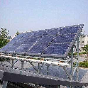
Why This Is Difficult
The parameters that decide wind load are known, and disputes on solar projects are almost never about the calculation method. They are about which parameter values were used.
- Terrain category and exposure change the basic wind speed substantially, so the same site classified two ways produces two different structures
- Uplift at array edges and corners can be two to three times the interior value, which makes zone-based fixing density the governing cost driver
- Module gap, tilt angle and array height all affect the pressure coefficients, so a layout change invalidates a load calculation
- Return period and risk category follow from the project classification, and getting that wrong is a compliance exposure rather than cost exposure
- Foundation capacity is usually governed by uplift rather than compression, so wind load determines pile depth as much as structure weight does
- Snow and wind can act together in some codes, and the combination is frequently overlooked in warmer climate projects
Engineering Requirements
These are the inputs we require to produce a defensible wind load calculation.
- Basic wind speed for the site with the source stated, together with the return period the project requires
- Terrain category or exposure classification, including how it changes across the site boundary
- Array geometry: module tilt, row pitch, array height above grade, module dimensions and the gaps between modules
- Site topography: escarpments, hills, ridges and any feature that produces local wind speed-up
- Risk category or consequence class, with the code edition referenced in the project jurisdiction
- Whether the design will be based on a code calculation or a wind tunnel study, and for which configuration
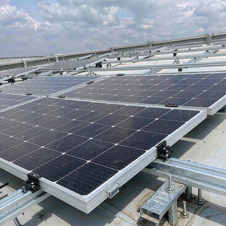
Selection guidance: state the terrain category and the return period explicitly in the specification. Most wind load disputes on solar projects are disagreements about these two values rather than about the calculation.
How We Solve It
- Zone-based uplift design, with interior, edge and corner zones calculated separately and fixing density stepped accordingly
- Terrain and topographic factors applied site-specifically, including local features that raise wind speed above the regional value
- Array height and module gap incorporated into the pressure coefficients rather than treated as constants
- Foundation uplift capacity designed against the calculated tension, so pile depth is driven by wind rather than by habit
- Combination load cases checked, including wind acting with snow or with seismic where the code requires it
- Calculation report issued with every structure package, stating the parameters used so a reviewer can reproduce the result
Beyond the Structure
- Sensitivity analysis on the governing parameters, so the buyer can see which input moves cost most before it is fixed
- Layout support: where a design is marginal, small changes to array height or row geometry often recover compliance more cheaply than added steel
Reference Benchmarks
Benchmarks below are publicly documented industry reference projects of comparable type and scale, cited to illustrate engineering practice. They are not our delivery record.
- A 200 MW project in the Philippines where a topographic speed-up factor at an escarpment required a foundation revision on one portion of the site only.
- A 250 MW site in the United States where zone-based uplift design reduced ballast and pile depth in the interior compared with a uniform-pressure approach.
- A 150 MW project in Turkey where the terrain category was reclassified after a site visit, changing the basic wind speed and the governing load case.
Standards and Compliance
- EN 1991-1-3 / ASCE 7 snow and ice load cases matched to your design return period
- IEC 61215 / IEC 61730 for module clamping zone and frame compatibility
- EN 1090 / AISC steelwork execution classes with weld procedure qualification records
- ISO 1461 galvanizing, ISO 12944 paint systems where duplex coating is specified
- ISO 9001 production quality management, batch traceability to heat numbers
- Local building code and permitting documentation support for your jurisdiction
Quality Assurance
Batch documentation is issued per lot: mill certificates traceable to heat numbers, galvanizing records with measured coating thickness, dimensional inspection reports from pre-assembly jigs and hardware lot traceability. Warranty covers named load cases and environmental exposure classes, so claims are settled against data rather than negotiation.
Documentation You Receive
Each shipment carries a document pack aligned to your asset register: certified material test reports, coating thickness records per batch, torque and preload verification sheets, packing lists with container numbers and a maintenance-relevant drawing set. Where the destination market requires local certification or translated documents, we prepare them in advance rather than at the port.
Service Life and Maintenance Planning
The economics of mounting systems are decided at year eight, not at signing. Galvanizing weight, fastener coating class and edge protection determine whether the year-eight inspection finds tight hardware or rust streaks. We publish expected first-maintenance intervals by environment class and back them with batch coating records, so warranty conversations start from data.
Cost and Commercial Considerations
- Wind load is the largest single driver of steel content in a ground-mount structure, and its effect is non-linear in high wind zones
- Zone-based design costs slightly more engineering time and typically saves more in steel and foundation than the engineering costs
- Wind tunnel testing carries a real cost but frequently recovers more tonnage than it costs on large arrays in marginal wind zones
- Terrain reclassification after a site visit occasionally moves a project between design categories and changes the budget materially
- Under-specifying the load case is not a saving, it is a contingency that surfaces as a compliance problem at permitting or lender review
Frequently Asked Questions
Why do the edges of an array need more steel than the centre?
Does terrain category really change the design?
When is a wind tunnel study justified?
What load case governs the foundation?
Can a layout change invalidate the calculation?
Related Guides and Application Pages
Continue with the pages closest to your project type.
What We Need to Quote
- Site coordinates or a location plan, with any topographic features and their approximate height
- Basic wind speed requirement and the code edition applicable in the project jurisdiction
- Terrain classification and how the site surroundings are classified
- Array geometry: tilt, module size, row pitch, array height and module gap
Talk to a Structure Engineer
Send the site location and the array geometry, and we will return a wind load basis stating the parameters used, a zoned uplift map and the fixing density implied for each zone.
