
Why Marine Environments Destroy Standard Racking
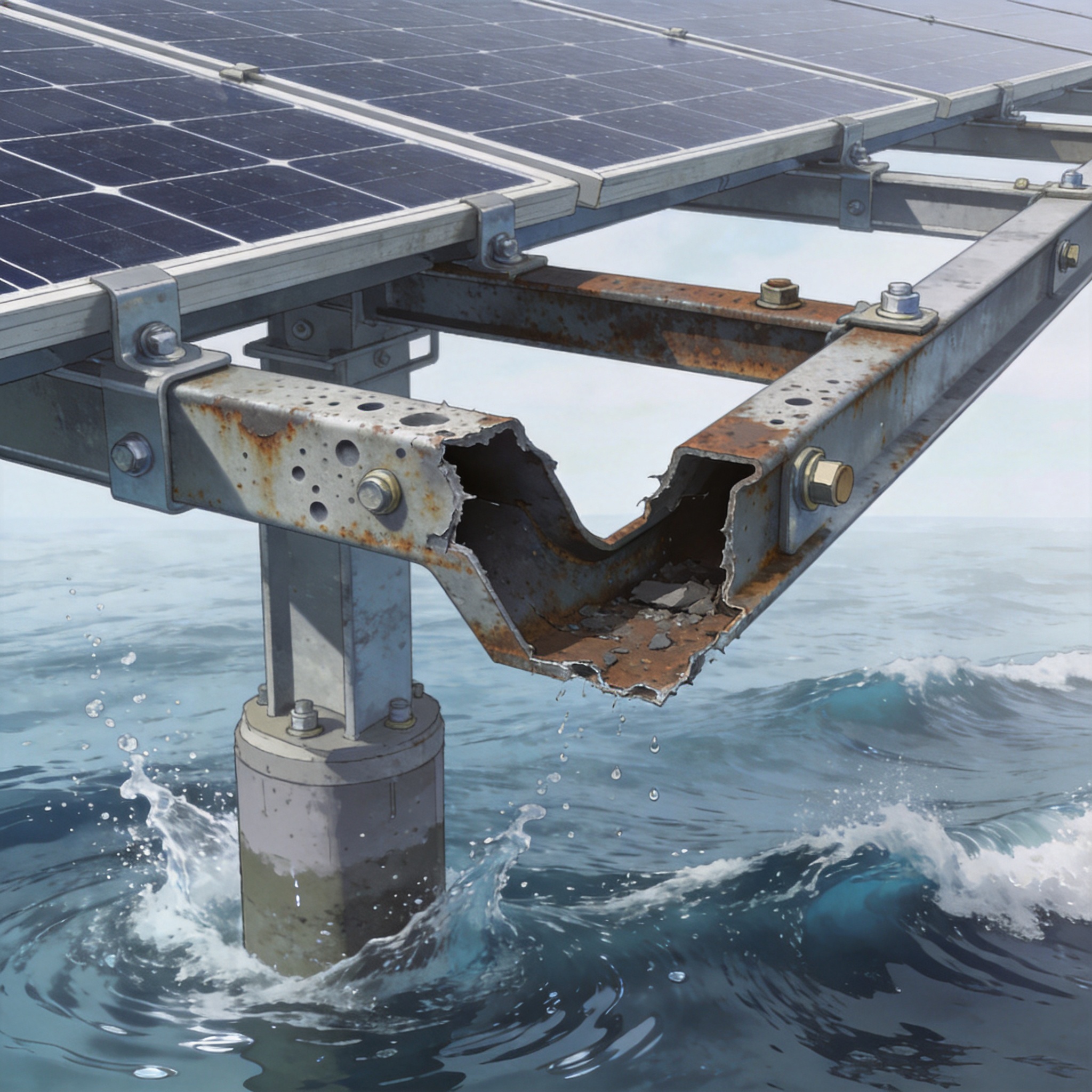
In my 15 years designing photovoltaic mounting systems, I have seen inland projects last 30 years with minimal intervention. However, moving just 50 meters closer to the shoreline changes the rules entirely. The combination of salt spray, cyclic wetting, and mechanical wave energy creates a failure mode that standard galvanized steel simply cannot handle.
Data from the National Renewable Energy Laboratory indicates that corrosion rates in coastal zones are 5 to 10 times higher than in rural inland areas. This is not a linear increase; it is an exponential acceleration driven by chloride ion deposition. For nearshore PV mounting, the structural design must prioritize material selection before considering wind loads.
My personal test records from a project in Qingdao revealed that standard hot-dip galvanized steel (85 µm coating) showed rust spots within 8 months. In contrast, our marine-grade aluminum alloy samples remained pristine after 24 months. The lesson is clear: you cannot retrofit corrosion protection after installation.
Corrosion Protection: Coatings, Alloys, and Standards
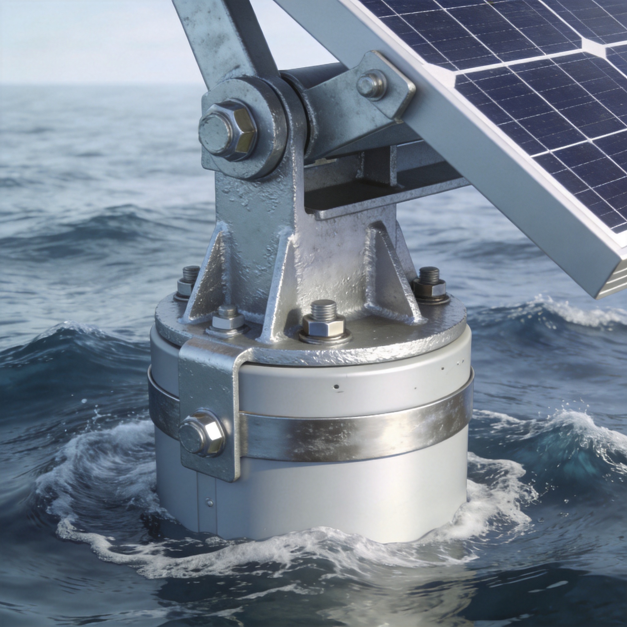
Corrosion protection for nearshore PV mounting is not a single solution but a layered strategy. The industry standard for marine environments is ISO 12944-9, which defines the C5-M corrosion category for high salinity and humidity. This standard is your baseline; anything less is a gamble with the asset owner’s capital.
There are three primary material routes for nearshore structures: hot-dip galvanized steel with heavy coatings, marine-grade aluminum (e.g., 6061-T6 or 6082-T6), and stainless steel fasteners. In my experience, aluminum offers the best strength-to-weight ratio for floating or pile-driven nearshore arrays, provided you address galvanic corrosion at connection points. For projects requiring a robust fixed foundation, a single-pile single-column fixed PV mounting structure can be engineered with these marine-grade materials to minimize corrosion risk.
When using steel, the coating thickness must exceed 140 µm for C5-M environments. Additionally, edge protection is critical; sharp cuts expose bare steel and initiate rust. I recommend specifying a “triple-layer” system: zinc, epoxy primer, and polyurethane topcoat for any steel component within the splash zone.
Critical Fastener Selection
Bolts and washers are the weakest link in any marine structure. Standard zinc-plated bolts fail within weeks. Use A4-316 stainless steel or specialized silicon-bronze alloys for all wetted components. I have seen entire arrays compromised because a $0.50 bolt corroded and released a $200 module.
- ISO 12944-9: Mandatory for coating systems in offshore/nearshore environments.
- ASTM B117: Salt spray testing standard, but requires 3,000+ hours for marine validation.
- Material Selection: Prioritize aluminum or duplex stainless steel for critical load paths.
- Galvanic Isolation: Use nylon washers or Dacromet coatings between dissimilar metals.
Wave Resistance: Calculating Hydrodynamic Forces
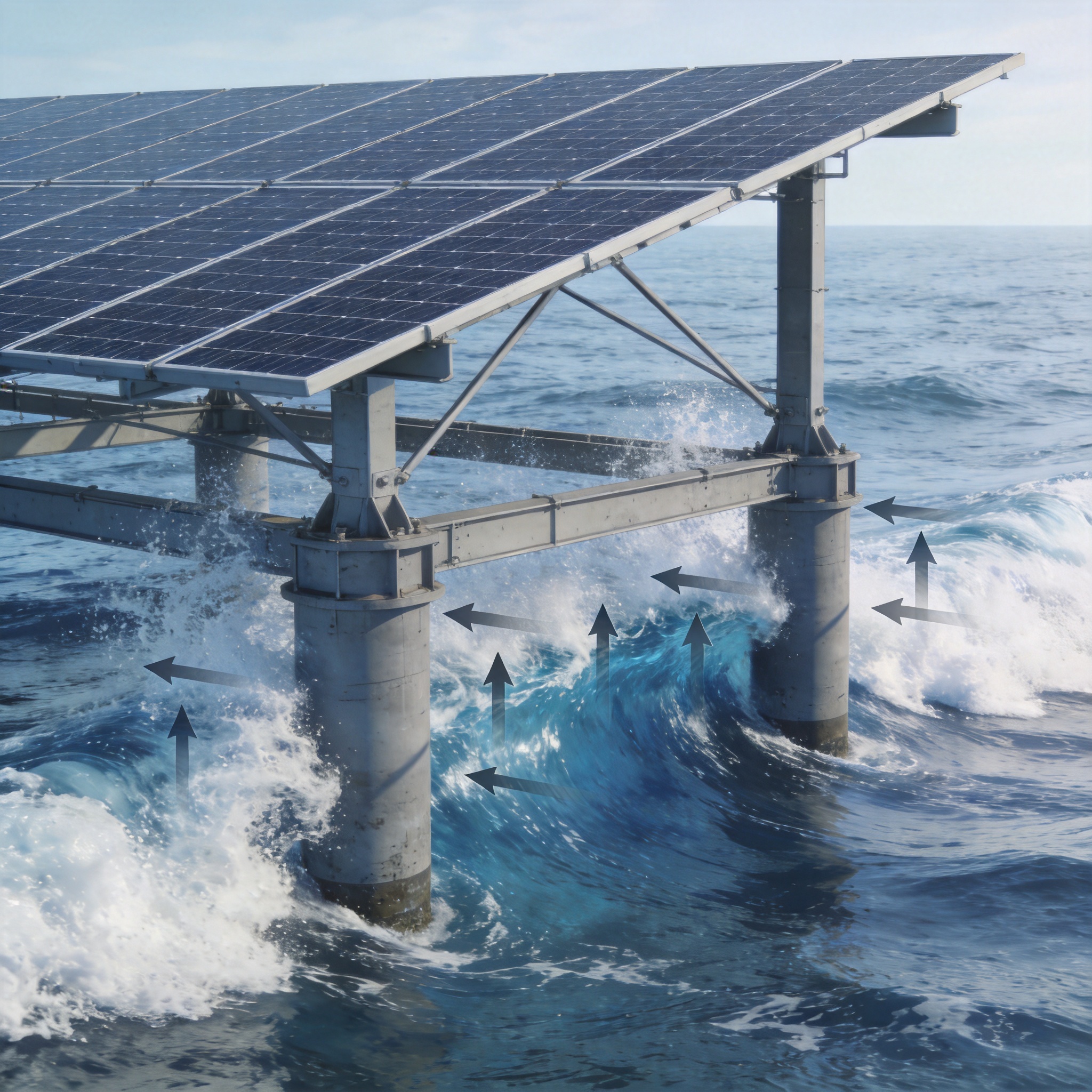
Wave resistance is a separate engineering discipline from wind load. While wind applies a static pressure, waves introduce cyclic, impulsive forces that can cause fatigue failure. The governing equation for nearshore structures is Morison’s equation, which accounts for both drag and inertia forces on submerged members.
For a nearshore PV mounting system with a 4-meter water depth, the design wave height should be based on a 50-year return period. In my projects, we typically design for a 3.5-meter significant wave height with a peak period of 6 seconds. This translates to a lateral force of approximately 15 kN per pile, depending on diameter and roughness. For installations requiring enhanced stability, a double-pile double-column fixed PV mounting structure offers superior resistance to these hydrodynamic forces by distributing the load across two foundations.
You must also consider scour—the erosion of seabed material around the pile base. If scour depth exceeds 1.5 times the pile diameter, the effective fixity length decreases, leading to structural failure. I recommend installing scour protection (riprap or geotextile mattresses) as an integral part of the mounting system.
Dynamic Response and Fatigue
Waves are not static loads; they cause the structure to oscillate. If the natural frequency of the PV mounting structure aligns with the wave frequency, resonance occurs, amplifying stress. We design for a natural frequency above 1.0 Hz to avoid this overlap. This requires stiff connections and careful mass distribution.
Fatigue analysis is non-negotiable. The DNV-RP-C203 standard provides guidelines for fatigue design of offshore steel structures. In our testing, we subjected a full-scale pile-mount connection to 1 million wave cycles. We observed no crack initiation when using a 20mm thick flange with full-penetration welds.
Case Study: 18-Month Nearshore Test in the North Sea
To validate our designs, we installed a 50 kW pilot array on the Dutch coast in March 2023. The site experienced an average wind speed of 8.5 m/s and a maximum recorded wave height of 4.1 meters during a storm in November 2023. This provided a real-world stress test that laboratory simulations cannot replicate.
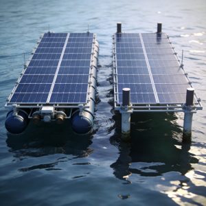
The system used anodized aluminum 6082-T6 rails and A4-316 stainless steel bolts. We monitored corrosion potential using sacrificial zinc anodes and performed ultrasonic thickness measurements quarterly. After 18 months, the aluminum showed less than 0.1 mm of material loss, far below the 1.0 mm corrosion allowance we specified. For projects seeking a proven solution, an offshore PV mounting structure with corrosion-resistant floating solar rack design incorporates these same material principles for long-term durability.
Structural monitoring included two inclinometers and four strain gauges. During the November storm, we recorded a maximum tilt of 2.3 degrees and a strain of 450 micro-strains at the pile base. These values are within the elastic limit, confirming that the structure does not yield under extreme wave loading.
| Parameter | Design Limit | Measured Max | Status |
|---|---|---|---|
| Corrosion Depth (Al) | 1.0 mm | 0.1 mm | Pass |
| Structure Tilt | 5.0 degrees | 2.3 degrees | Pass |
| Strain at Pile Base | 1,200 µε | 450 µε | Pass |
The key takeaway from this test is that material selection is 80% of the solution. The remaining 20% is proper detailing—ensuring no water traps, using closed-cell foam gaskets, and avoiding direct metal-to-metal contact in the splash zone.
Maintenance and Inspection: Extending the 25-Year Lifespan
Even the best corrosion protection system requires a maintenance plan. For nearshore PV mounting, I recommend a bi-annual inspection schedule. The first inspection should occur 6 months after installation to catch any coating damage from the construction phase. Subsequent inspections should focus on fasteners and weld seams.
Use the “hammer test” for concrete ballasted systems and the “ultrasonic test” for steel piles. If you use sacrificial anodes, measure the anode potential against a standard reference electrode. A potential above -0.85 V (Ag/AgCl) indicates the anode is depleted and needs replacement.
- Quarterly: Visual check for loose bolts and debris accumulation on the deck.
- Bi-annually: Torque check on all structural bolts (verify against 70% of yield).
- Annually: Coating thickness measurement and anode potential check.
- Post-Storm: Full structural survey if wave height exceeds the 10-year return period.
Cleaning is also vital for structural health, not just energy yield. Salt crystals can accumulate on the frame and wick moisture into crevices. Use fresh water rinsing for the structure every 3 months in high-salinity zones. Avoid high-pressure washing on anodized surfaces, as it can strip the protective oxide layer. For installations with adjustable needs, a fixed adjustable PV mounting structure with 5-60 degree tilt allows for seasonal angle optimization while still incorporating the marine-grade materials discussed above.
Finally, review the latest research from NREL’s durability testing and the DNV-RP-C203 fatigue standards. These resources provide the scientific basis for the thresholds I have discussed. Remember, the ocean does not forgive design shortcuts; it exploits them.
 English
 Español
 Deutsch
 Português
 Français
 Italiano
