



Warum das schwierig ist
Driven piles fail in a small number of recognisable ways, and each one traces back to a decision taken before installation started.
- Soil profiles vary across a site far more than a single borehole suggests, so refusal can appear in one zone while adjacent zones drive freely
- Over-driving damages the pile head or the coating, and the damage is usually invisible until the structure is loaded
- Pile position and plumb tolerance determine whether the structure assembles without rework, because racking adjustment ranges are finite
- Pull-out and lateral capacity depend on soil friction, which changes with moisture content and cannot be verified after driving
- Coating damage at the ground line is the most common long-term durability failure on driven piles and the hardest to inspect
- Driving productivity sets the construction programme, so pile refusal is a schedule event rather than a technical inconvenience
Technische Anforderungen
These are the inputs that decide driven pile section, depth and method.
- Geotechnical investigation with boreholes or cone penetration tests at a density reflecting the site’s variability, not a single central hole
- Soil classification and corrosivity testing, since both the design embedment and the coating class depend on them
- Design uplift, compression and lateral loads per pile, derived from the structural load case and foundation layout
- Pile section, wall thickness and steel grade selected against both design load and the driving stresses the method will impose
- Driving method and equipment: impact or vibratory, hammer energy, and the refusal criterion to be applied
- Verification protocol: static or dynamic load testing sample rate, and acceptance criteria for production piles
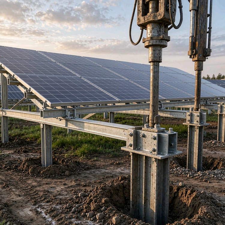
Selection guidance: fix the pile section from the geotechnical data and then choose the driving method to suit the soil. Choosing equipment first and designing the pile to survive it is how coating damage and refusal enter a project.
Wie wir es lösen
- Pile sections selected against both design load and driving stress, so the pile that carries the load also survives installation
- Embedment depth derived from site soil friction and bearing values, with zone-by-zone depths where the profile changes
- Driving method matched to the soil: impact for dense strata, vibratory where displacement is acceptable and speed matters
- Coating specification stepped by soil corrosivity, with additional protection at the ground line where abrasion concentrates
- Tolerance control through template jigs and position surveying, keeping pile heads inside the structure adjustment envelope
- Verification by testing a defined sample, with production acceptance criteria tied to logged driving records
Jenseits der Struktur
- Driving records logged per pile, so refusal zones and over-driving are visible during installation rather than discovered at commissioning
- Pile head detailing that accommodates re-levelling after settlement, avoiding foundation rework in the first operating years
Referenz-Benchmarks
Die folgenden Benchmarks sind öffentlich dokumentierte Branchenreferenzprojekte vergleichbarer Art und Größenordnung, die zur Veranschaulichung der Ingenieurpraxis dienen. Sie stellen nicht unsere Leistungsbilanz dar.
- A 300 MW project in Chile where vibratory driving was selected after impact driving produced coating damage in the upper soil layer.
- A 180 MW site in Spain with variable calcarenite bands, where zone-specific embedment depths avoided a refusal problem that a single uniform depth would have created.
- A 250 MW project in the United States using dynamic load testing on a defined sample, replacing a larger static test programme without changing the design basis.
Standards und Konformität
- ASCE 7 / EN 1991 Windlastkombinationen und EN 1998 / IBC Erdbebenlastkombinationen, sofern anwendbar
- Die mechanischen Belastungstestpegel gemäß IEC 61215 sind auf den Auslegungsdruck Ihres Arrays abgestimmt.
- Ausführungsklassen nach EN 1090-1/-2 oder AISC für Bauteile aus Stahl
- ISO 1461 Verzinken mit Zinkmasse, gestaffelt nach Korrosivitätskategorie C2 bis C5
- Qualitätsmanagement nach ISO 9001:2015 und dokumentierte Lieferantenqualifizierung
- Unterstützung durch DNV oder eine gleichwertige Bankfähigkeitsprüfung für finanzierte Projekte
Qualitätssicherung
Die Chargendokumentation wird chargenweise ausgestellt: Werkszeugnisse mit Rückverfolgbarkeit zu den Chargennummern, Verzinkungsprotokolle mit gemessener Schichtdicke, Maßprüfberichte von den Vormontagevorrichtungen und Chargenrückverfolgbarkeit der Hardware. Die Garantie deckt bestimmte Lastfälle und Umwelteinwirkungsklassen ab, sodass Ansprüche anhand von Daten und nicht durch Verhandlungen reguliert werden.
Dokumentation, die Sie erhalten
Jede Sendung enthält ein auf Ihr Anlagenverzeichnis abgestimmtes Dokumentenpaket: zertifizierte Materialprüfberichte, Aufzeichnungen zur Beschichtungsdicke pro Charge, Prüfprotokolle für Drehmoment und Vorspannung, Packlisten mit Containernummern und einen Satz wartungsrelevanter Zeichnungen. Falls der Zielmarkt lokale Zertifizierungen oder Übersetzungen von Dokumenten erfordert, erstellen wir diese im Voraus und nicht erst im Hafen.
Lebensdauer- und Wartungsplanung
Die Wartung sollte anhand messbarer Kriterien und nicht anhand von Schätzungen im Kalender erfolgen: jährliche Sichtprüfung der Anzugsmomente von Befestigungselementen, Zustand der Beschichtung an Schnittkanten und Erdungskontaktstellen; eine detaillierte Prüfung nach dem ersten Jahr mit extremen Witterungsbedingungen; und Überprüfung des Anzugsmoments nach dem ersten Temperaturzyklus bei langen Strecken. Die Prüfcheckliste und die Abnahmekriterien stellen wir zusammen mit der Installationsanleitung zur Verfügung.
Kosten- und kommerzielle Überlegungen
- Pile steel is quoted per tonne, but the number that governs project cost is piles per day, which is a function of the soil rather than of the price
- Under-investing in geotechnical investigation is the most expensive saving on a driven pile project, because it converts a design problem into a construction problem
- Coating upgrades at the ground line are a small unit cost with a large effect on year-ten maintenance
- Dynamic load testing is substantially cheaper per pile than static testing and can be applied at higher sample rates for the same budget
- Refusal and re-driving are schedule costs, and a single day of pile rig downtime on a 200 MW site is material against the energisation date
Häufig gestellte Fragen
How do you decide embedment depth?
Impact or vibratory driving?
How do we know the piles will hold?
What pile position tolerance can the structure accept?
Does pile driving damage the coating?
Verwandte Leitfäden und Anwendungsseiten
Fahren Sie mit den Seiten fort, die Ihrem Projekttyp am ehesten entsprechen.
Was wir für ein Angebot benötigen
- Geotechnical investigation report including borehole logs, soil classification and corrosivity results
- Design uplift, compression and lateral load per pile, with the foundation layout
- Pile section, length and coating class currently assumed, if already defined
- Available driving equipment and any site access constraints that limit rig size
Sprechen Sie mit einem Statiker
Send the geotechnical report and the foundation layout, and we will return a pile section recommendation, zone-by-zone embedment depths and a verification protocol sized to your site.
 English
 Español
 Deutsch
 Português
 Français
 Italiano