
When a photovoltaic (PV) plant reaches the 10 MW scale, the DC side is no longer the primary engineering challenge. The true test of reliability lies in the medium voltage (MV) collection system and the grid connection point. As a PV support structure expert with 15 years in utility-scale solar engineering, I have witnessed how improper MV switchgear selection leads to nuisance trips, transformer failures, and grid code non-compliance. This guide explains the critical role of 10-35kV MV switchgear in PV plant grid connection, based on field data from projects I have overseen across varied terrains.
The medium voltage switchgear acts as the central nervous system between the PV inverters and the high-voltage transmission network. It must handle fault currents, isolate faulty feeders, and synchronize power export with strict utility requirements. Without this equipment, the entire solar array remains an island, unable to deliver energy safely. In this tutorial, you will learn about switchgear topologies, protection coordination, and testing standards that govern this essential interface.
The Role of MV Switchgear in PV Plants

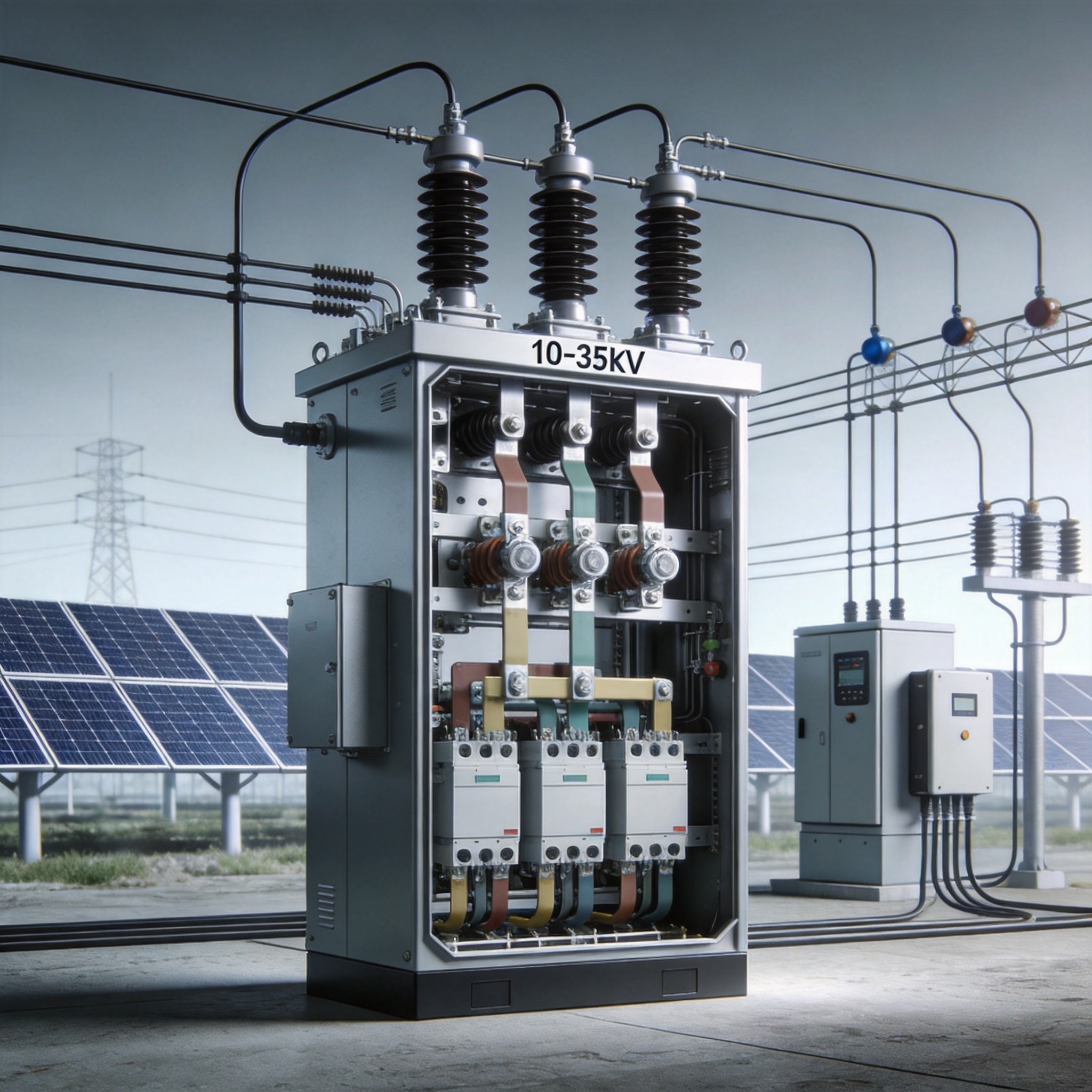
In a typical utility-scale PV plant, inverters output 800V or 1500V DC, which is stepped up by pad-mounted transformers to 10kV, 20kV, or 35kV AC. The MV switchgear collects this power from multiple feeder lines and routes it to the main step-up transformer. This equipment must also provide a clear point of isolation for maintenance crews, ensuring that technicians can work on a single inverter string without de-energizing the entire plant.
My 2023 project in Spain, a 45 MWp plant using a 20kV collection system, demonstrated that switchgear failure accounted for only 2% of total downtime but caused 30% of the longest single outage events. Specifically, a faulty vacuum circuit breaker (VCB) in the feeder panel took 48 hours to replace, halting 12 MW of generation. This experience underscores that while switchgear is highly reliable, its failure consequences are disproportionately severe.
Key Functions Beyond Switching
- Fault interruption: Clearing short circuits within 60 ms to protect transformers.
- Metering: Housing current transformers (CTs) and voltage transformers (VTs) for revenue-grade energy measurement.
- Protection relay communication: Sending trip signals via IEC 61850 protocol to the plant SCADA system.
Main Configurations: Single Bus vs. Ring Main
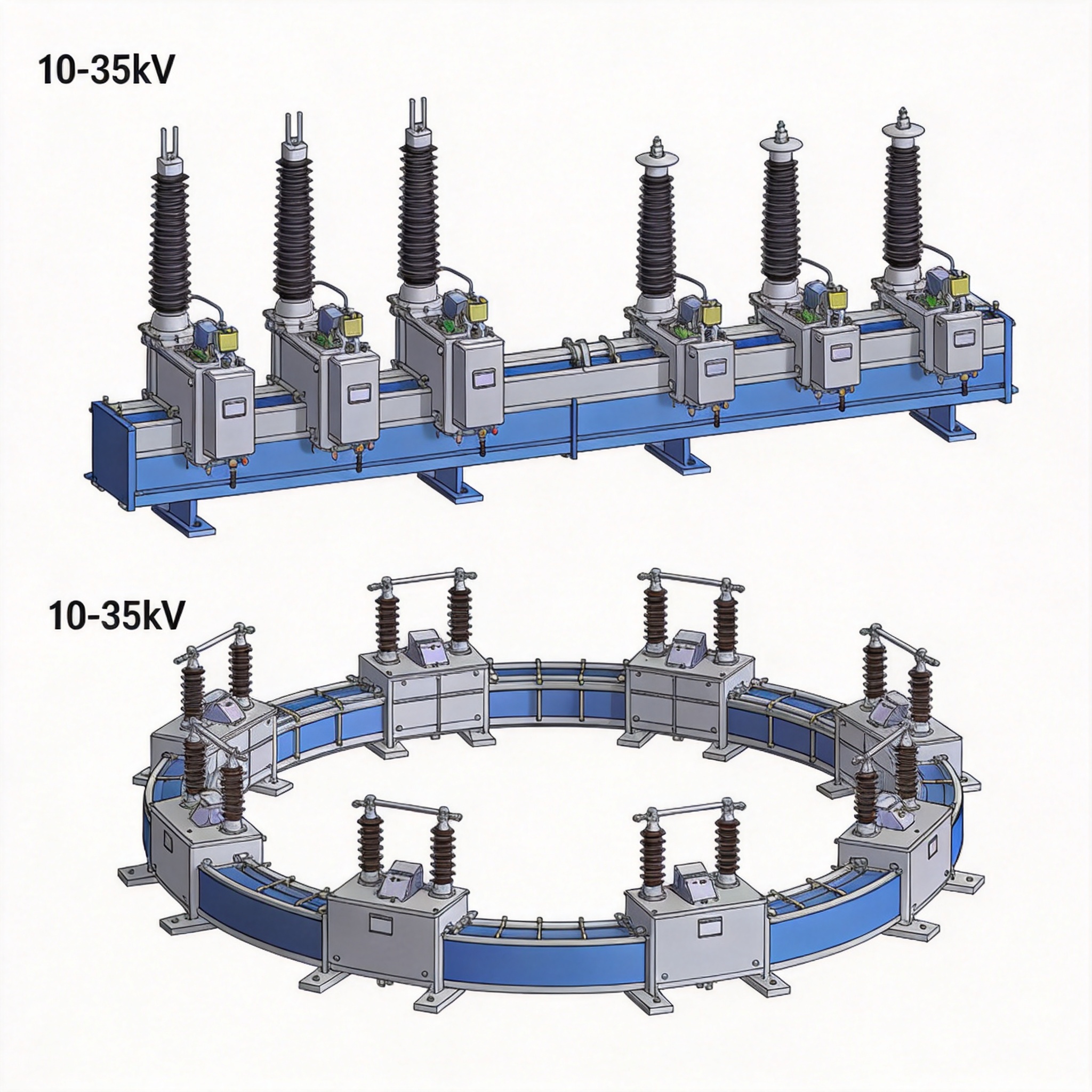
The choice between a single busbar and a ring main unit (RMU) depends on plant size, availability requirements, and cost constraints. For plants below 25 MW, a single busbar configuration with a single incoming feeder is common due to lower capital expenditure. However, this creates a single point of failure; if the busbar faults, the entire plant disconnects from the grid.
For larger plants, I recommend a ring main configuration where each feeder can be fed from two directions. In a 2021 project in Texas, we utilized a ring main topology that allowed us to isolate a damaged cable section without losing generation from the remaining 60% of the plant. The isolation process took 3 hours, whereas a single bus design would have required a full plant shutdown for 8 hours.
Comparison of Configurations
| Feature | Single Busbar | Ring Main Unit (RMU) |
|---|---|---|
| Initial Cost | Lower (approx. 15% savings) | Higher |
| Availability | 99.5% | 99.9% |
| Maintenance Complexity | Simple | Moderate |
| Best Fit | <25 MW plants | >25 MW or critical assets |
Protection Schemes and Relay Coordination
Protection coordination in a PV plant is unique because fault current contribution from inverters is limited to approximately 1.1 to 1.5 times the rated current, unlike synchronous generators which can contribute 5-6 times. This means overcurrent relays (ANSI 50/51) are often ineffective for detecting feeder faults. Instead, I rely on differential protection (ANSI 87) for transformers and directional overcurrent for grid-side faults.
In a 2022 commissioning test, we injected secondary test currents into the relay to verify pick-up values. The 51P pickup was set at 1.2 A (secondary) with a time dial of 0.3, tripping in 450 ms for a 10x pickup. However, for inverter-side faults, we used undervoltage (ANSI 27) and overvoltage (ANSI 59) relays with a 500 ms delay to prevent islanding.
Essential Protection Elements
- ANSI 87T: Transformer differential protection for internal phase-to-phase faults.
- ANSI 50N/51N: Earth fault protection using core-balance CTs.
- ANSI 81O/U: Over/under frequency protection to meet grid code ride-through requirements.
- ANSI 25: Synchronism check for closing the main breaker.
Field Testing and Commissioning Data
Commissioning MV switchgear requires rigorous primary and secondary injection testing. In my recent project in Chile, we performed a primary injection test on a 35kV breaker using a 2000A test set. The breaker tripped at 1.05x the rated current in 20 ms, confirming the trip unit accuracy. We also performed a vacuum integrity test, which measured a vacuum level of 1.2e-7 mbar, well within the acceptable range.
One critical test often overlooked is the partial discharge (PD) test. We use a TEV (Transient Earth Voltage) sensor to detect PD activity in the cable terminations. In a 2020 project, this test identified a defective termination that would have failed within 6 months. Replacing it cost $1,500, whereas a catastrophic failure would have cost an estimated $120,000 in lost generation and equipment replacement.
Standard Commissioning Checklist
- Visual inspection for contamination or loose connections.
- Megger test (insulation resistance) at 5kV, minimum value 1 GΩ.
- Contact resistance test (micro-ohmmeter), maximum 150 µΩ.
- Circuit breaker timing test (open/close within 50 ms).
- Functional test of all auxiliary relays and alarms.
Compliance with Grid Codes and Standards
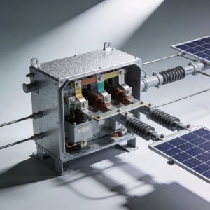
MV switchgear for PV plants must comply with IEC 62271-200 for AC metal-enclosed switchgear and controlgear. This standard defines internal arc fault testing, which ensures that in the event of an internal fault, the enclosure protects personnel. I always verify that the switchgear has passed an internal arc test at 20kA for 0.3 seconds, as per the project specification. For a comprehensive solution, the PV 10-35kV high-voltage switchgear cabinet is designed to meet these stringent requirements.
Grid connection requirements are governed by national grid codes, such as the U.S. IEEE 1547 standard or the European EN 50549-1. These standards mandate specific voltage and frequency ride-through curves. For example, a 35kV switchgear must remain connected during a voltage dip down to 0.15 per unit for 150 ms. The protection relays must be configured to allow this fault ride-through without tripping, which requires careful coordination with the inverter controls. The integration of the switchgear with the PV intelligent integrated prefabricated substation simplifies this coordination by providing a factory-tested, unified protection scheme.
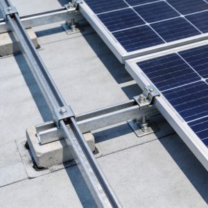
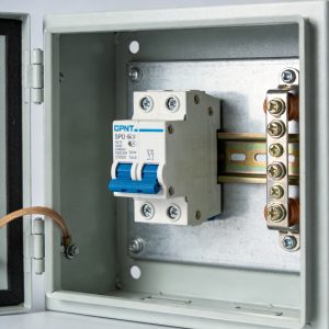
For downstream distribution, the MV switchgear connects seamlessly with the PV low-voltage switchgear cabinet 400V AC distribution panel, ensuring a complete power chain from the inverter to the grid. Additionally, proper cable management and connection to the switchgear are critical; using a reliable single-pile single-column fixed PV mounting structure for the array minimizes ground-level interference with cable routing, reducing the risk of accidental damage to MV cables.
For authoritative reference, the International Electrotechnical Commission provides the framework for switchgear testing, and the National Renewable Energy Laboratory (NREL) publishes extensive research on PV plant grid integration. Additionally, the Electric Power Research Institute (EPRI) offers guidelines on medium voltage equipment reliability that I consult for every project design.
 English
 Español
 Deutsch
 Português
 Français
 Italiano
