




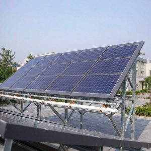
What This Group Covers
That combination rewards standardisation over optimisation. Repeatable kits, one rail family and a design that copies cleanly from site to site beat a bespoke structure that saves a few percent on steel but costs weeks in engineering each time.
- Community solar garden racking for 1-20 MW shared-ownership and subscription projects
- Utility-owned distributed assets, where long-term maintenance access matters more than first cost
- Landfill, brownfield and contaminated-land arrays where excavation and penetration are restricted
- Standardised kit design for developers building repeatable portfolios rather than one-off plants
- Interconnection-driven layout: how the grid connection point shapes the array rather than the other way round

Three Configurations to Start From
Three supply configurations cover most community solar and DG cases:
Standard line
Hot-dip galvanized steel table, driven piles, kit-based delivery. Best for: Straightforward greenfield community gardens. Relative cost: 1.0 (baseline).
Low-impact line
Ground screws or ballasted bases, minimal surface disturbance. Best for: Landfill caps, brownfield and restricted-tenure land. Relative cost: +15 to +28%.
Portfolio line
Standardised kit with locked rail family and common drawings across sites. Best for: Developers building repeatable 5-20 site programmes. Relative cost: -5 to -12% at programme level.
Why community solar and DG projects are demanding
Distributed generation projects fail on site conditions and land tenure far more often than on technology. The array is usually the second or third use proposed for the land, the lease may run for less than the asset life, and the interconnection capacity is fixed before the layout is drawn.
- Available land is often the site nobody else wanted – a closed landfill, a former industrial yard, land with easements crossing it
- Interconnection capacity at the point of connection caps the array size, so land is rarely the binding constraint and layout must fit the grid rather than the fence
- Lease terms may be shorter than the asset life, which changes what counts as a reasonable foundation investment
- Small projects still need the full compliance set – permitting, code compliance, documentation – so engineering hours per megawatt run far higher than on utility work
- Subscriber or tariff revenue models are sensitive to shading loss, so row spacing has to protect yield rather than maximise capacity per acre
Engineering Requirements
The design basis for distributed generation is driven by land and tenure rather than by load. These are the checks that protect the investment case.
- Land-use constraints mapped first: easements, setbacks, wetland buffers and any deed restrictions on the parcel
- Foundation method matched to land status – no penetration on capped landfills, and low-disturbance methods on contaminated ground
- Layout optimised against the interconnection capacity rather than the fence line, with DC/AC ratio agreed before layout freeze
- Shading and row-pitch study to protect yield at the specific tariff or subscription structure of the project
- Standardised kit design so that drawing sets and construction methods carry across a portfolio without re-engineering
- Decommissioning and reversibility considered at design stage where the lease requires site restoration
Selection guidance: get the land-use constraints and the interconnection capacity in writing before layout. Both are more expensive to accommodate after the design is frozen.
Key Parameters
| Parameter | Typical specification |
|---|---|
| Deployment | Ground-mount fixed-tilt, low-tilt or short tracker runs |
| Capacity band | 1-20 MW per site; 2-6 MW typical for single community gardens |
| Foundation options | Driven piles, ground screws, ballasted bases where penetration is restricted |
| Array density | Land use typically 4-8 acres per MW at mid-latitude with tracker or low-tilt fixed |
| DC/AC ratio | 1.15-1.35 typical for distributed projects with subscription or tariff revenue |
| Interconnection | Layout driven by point-of-connection capacity, not by available land area |
| Code basis | Local permitting plus ASCE 7 or EN 1991 wind; state or national incentive scheme requirements |
| Standardisation | One rail and clamp family per portfolio, one spares kit, one install procedure |
How We Deliver It
- A standard kit architecture that a developer can reuse across sites, with limited variables for soil, wind and capacity
- Non-penetrating and low-disturbance foundation options for landfill capping and contaminated ground
- Layout produced from the interconnection capacity backwards, so the array matches the approved export limit
- Row pitch tuned to the revenue structure: protecting yield where tariffs reward it, and maximising density where capacity is capped
- Documentation packs aligned to incentive scheme and permitting requirements, issued per site but from a common template
- Reversibility designed in where leases require restoration, using recoverable piles and above-ground cable routing
Standards and Compliance
- EN 1991-1-3 / ASCE 7 snow and ice load cases matched to your design return period
- IEC 61215 / IEC 61730 for module clamping zone and frame compatibility
- EN 1090 / AISC steelwork execution classes with weld procedure qualification records
- ISO 1461 galvanizing, ISO 12944 paint systems where duplex coating is specified
- ISO 9001 production quality management, batch traceability to heat numbers
- Local building code and permitting documentation support for your jurisdiction
Quality Assurance
Quality control is checkpoint-based: material intake verification, in-process weld and hole-position inspection, coating thickness sampling and pre-shipment container review. Each checkpoint produces a document your quality team can file, and pre-shipment inspection is open to your inspector or a third party.
Installation and Site Productivity
The installation method is part of the technical proposal, not an afterthought. We state the equipment needed, the crew composition, the expected daily output and the tolerance acceptance criteria for every structural interface. Pre-assembled kits are labelled to your build sequence, fasteners are supplied in matched lots with torque values, and the design avoids site welding entirely. Where a project needs accelerated schedules, we plan multiple parallel work fronts and split kits accordingly.
Documentation You Receive
Each shipment carries a document pack aligned to your asset register: certified material test reports, coating thickness records per batch, torque and preload verification sheets, packing lists with container numbers and a maintenance-relevant drawing set. Where the destination market requires local certification or translated documents, we prepare them in advance rather than at the port.
Cost and Commercial Considerations
- Engineering cost per megawatt is the hidden driver at this scale: standardisation typically removes 30-50 percent of per-site design effort
- Low-impact foundation methods add 15-28 percent on structure but are often the only approval path on restricted land
- Row pitch decisions move annual yield by 3-8 percent, which usually outweighs small changes in steel tonnage
- Permitting and documentation effort is largely fixed per project, so it is proportionally far heavier than on utility work
- Lead time: 3-6 weeks for standardised kits, 5-9 weeks where low-impact foundations or landfill detailing are needed
Reference Benchmarks
- A 6 MW community solar portfolio across four sites in the north-eastern United States, standardised on a single kit family so construction crews moved between sites without retraining.
- A 3 MW solar garden built on a closed landfill in Italy, using ballasted foundations with a geotextile separation layer and above-ground cable routing.
- A 5 MW distributed project in Japan on former industrial land, low-tilt fixed tables with close row pitch to fit the interconnection limit inside the parcel boundary.
- A 12 MW utility-owned distributed programme in Australia, designed for long-term maintenance access with walkway routes and standardised spare-part packaging.
Service Life and Maintenance Planning
Service life is a design output, not a promise. Zinc mass, fastener coating class, drainage detailing and dissimilar-metal isolation are selected against the corrosivity category of your site, and the expected first-maintenance interval is stated in writing. For aggressive environments we step the coating system up at design stage, which is always cheaper than a retrofit.
How We Control Delivery
| Stage | What we do | What you receive |
|---|---|---|
| Land review | easements, setbacks and land-status restrictions mapped against the layout | constraint map and exclusion zones |
| Interconnection match | array capacity and DC/AC ratio confirmed against the approved export limit | capacity statement and layout confirmation |
| Material intake | steel grade, coating mass and fastener class verified per batch | mill certificates and coating records |
| Pre-shipment | kit completeness and labelling by array block reviewed against the build sequence | packing list and loading photos |
| Site handover | foundation positions, torque values and restoration provisions confirmed | installation manual, as-built set and warranty letter |
Send your parcel boundary and interconnection limit – we will return a layout concept, foundation options and a standardised kit proposal for your portfolio.
Guides in This Group
Community Solar Garden Racking Systems
Repeatable kit design for subscription and shared-ownership solar gardens.
Utility-Owned Distributed Solar Racking
Long-horizon assets where maintenance access and spares availability outrank first cost.
Solar Racking on Landfill & Brownfield Sites
Non-penetrating and low-disturbance foundations for capped and contaminated land.
Related Application Directories
This scale band is often combined with the following application groups, which cover terrain, land type and site conditions.
Frequently Asked Questions
Can you supply a non-penetrating foundation for a capped landfill?
How do you keep engineering cost down across a portfolio?
Our interconnection capacity is smaller than the land area allows. What should we do?
Is a tracker worth it at 3 or 5 MW?
How does the lease term affect the foundation choice?
What We Need to Quote
- Parcel boundary, acreage and any easements or deed restrictions on the land
- Approved interconnection capacity and the target DC/AC ratio
- Site status: greenfield, brownfield, capped landfill or former industrial use
- Revenue structure and expected operating term, so row pitch and foundation life can be matched to it
Talk to a Structure Engineer
Send your site data, target capacity and construction programme, and our engineers will return a structure concept, a quantity estimate and a costed supply package.
