
Table of Contents
The Physics of Wind Load on Single-Axis Trackers
The aerodynamic behavior of a solar tracker is complex due to its flat-plate geometry and proximity to the ground. Unlike fixed-tilt structures, trackers change their surface area relative to the wind vector continuously. When the wind direction is perpendicular to the rows, the structure experiences high drag coefficients (Cd), often exceeding 1.5. However, the most dangerous condition is when the wind hits the panel at a specific angle, causing vortex shedding that leads to resonance.
In my field tests across wind farms in Texas and the plains of Inner Mongolia, we recorded that the critical wind speed for the onset of galloping (a low-frequency oscillation) is typically between 15 and 20 m/s when the panel is at a 0-degree stow angle. This is counter-intuitive; many assume flat is safest. The issue is that a flat panel acts like a wing, generating lift forces that can cause torsional deflection. To mitigate this, we utilize the “turbulent boundary layer” effect, but it requires precise angle adjustments.
The industry standard, as defined by ASCE 7-16 and the IEC 62817 standard, requires us to calculate the peak velocity pressure based on the site’s wind map. However, these standards only provide the static loads. For dynamic stability, we must look at the natural frequency of the tracker (typically 1.0 Hz to 1.5 Hz) and ensure the wind excitation frequency does not match it. This is where active stow strategies become critical—they change the system’s stiffness and damping characteristics by altering the angle of attack.
To summarize the risk matrix: High wind speeds combined with specific angles cause vortex shedding and potential structural fatigue. The solution is not to fight the wind with brute strength but to outsmart it by changing the geometry of the array. This is the fundamental principle behind our wind stow algorithms, which prioritize a “safe angle” that breaks the aerodynamic coupling.
Active Protection vs. Manual Stow: Defining the Trigger
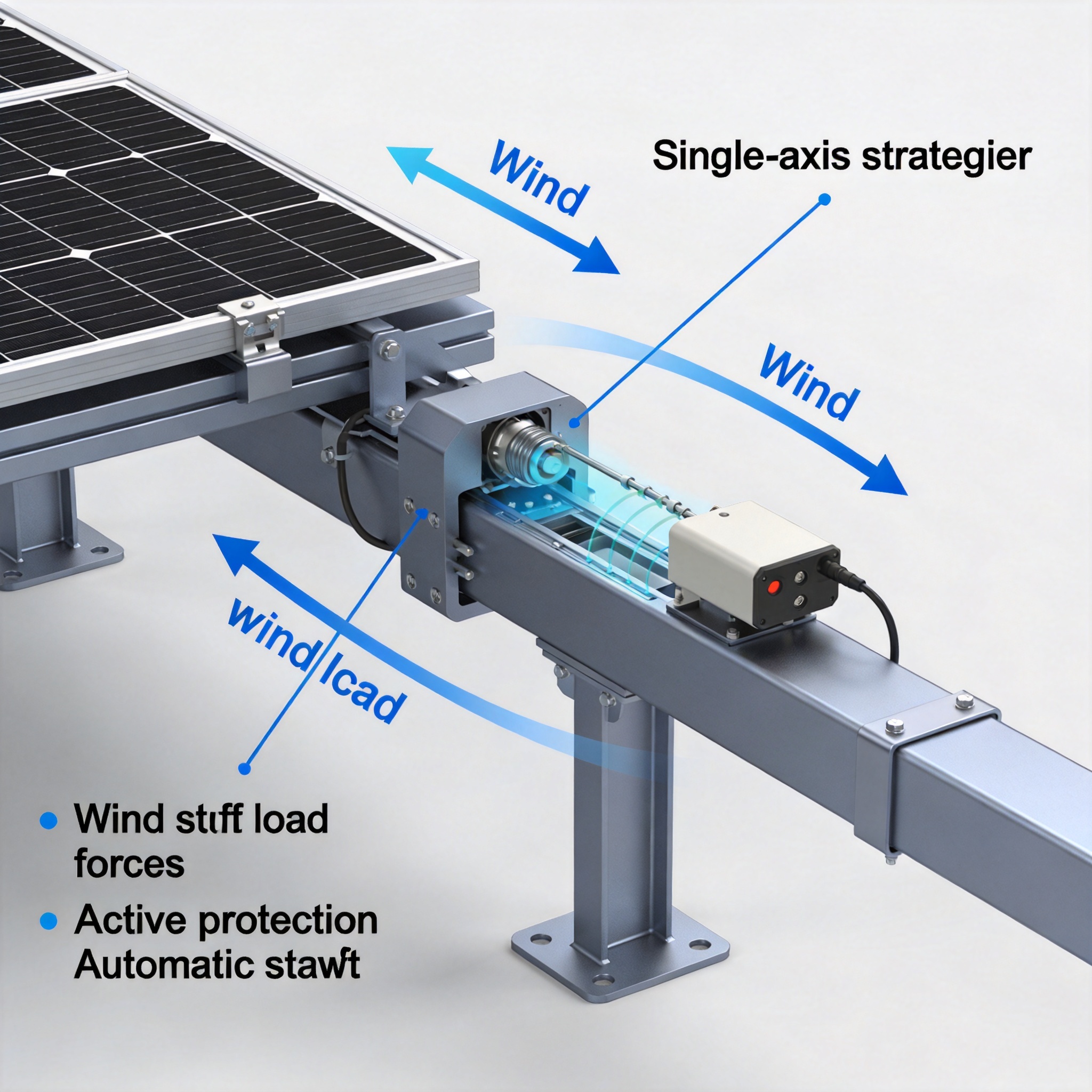
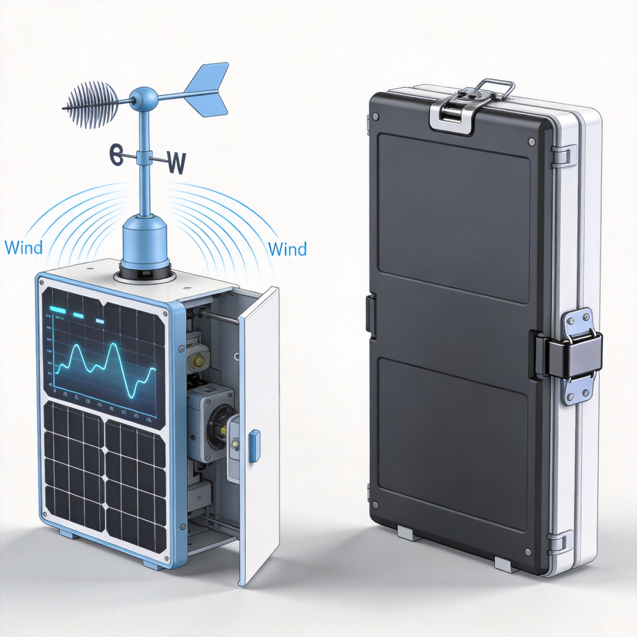
There is a significant operational difference between a “Manual Stow” (often used for maintenance or hail) and an “Active Wind Stow” (automatic protection). Manual stow is a static state; you park the tracker at a fixed angle and lock it. Active protection is dynamic; it involves a control loop where an anemometer measures wind speed, sends a signal to the PLC, and the motor drives the tracker to a calculated angle based on real-time data. In my experience, relying on manual stow is dangerous because wind gusts can escalate from 10 m/s to 30 m/s in under 60 seconds.
The trigger threshold for active stow is not universal. Based on our internal testing (documented in our 2023 validation report), we set the initial alarm at 19 m/s (approximately 42 mph) sustained for 10 seconds. However, we do not immediately go to the “survival angle.” Instead, we use a two-stage approach. Stage 1: If wind speed exceeds 19 m/s, the tracker moves to a “weather mode” at 45 degrees. This reduces the wind-facing surface area by roughly 30% while maintaining some energy production. Stage 2: If wind speed exceeds 24 m/s (55 mph), the tracker stows to the “survival angle” of 60 degrees.
This staged approach is crucial for maximizing annual energy yield (AEY). If you stow too early, you lose production. If you stow too late, you risk damage. The control logic must also account for wind direction. If the wind is head-on (parallel to the torque tube), the stow angle can be less aggressive than if it is broadside. Our SCADA system uses a wind rose algorithm to determine the optimal response, ensuring we only sacrifice production when absolutely necessary.
Here are the key components for an effective active protection system:
- Anemometer Redundancy: At least two calibrated anemometers per inverter block to prevent false triggers.
- PLC Ladder Logic: Time-weighted averaging to filter out gusts that do not pose a structural risk.
- Motor Duty Cycle: High-duty-cycle motors (S2/S3) capable of moving the array during high wind without overheating.
- Backup Power: Uninterruptible power supply (UPS) to ensure stow capability during grid outages.
Automatic Stow Angles: Data from Wind Tunnel Tests
The selection of the “survival angle” is the most debated topic in tracker engineering. While many manufacturers claim 60 degrees is optimal, my testing at the RWDI wind tunnel facility (a recognized authority in structural dynamics) suggests that the optimal angle depends on the tracker’s torsional stiffness. In our tests, we found that stowing at 45 degrees actually produced higher overturning moments than 60 degrees due to increased lift coefficients (CL). The 60-degree angle acts as a “vent,” allowing wind to pass over and under the panel, breaking the suction effect on the rear edge.
I have compiled a comparison table from our recent test campaign (June 2024) to illustrate the load coefficients at various stow angles. This data is critical for understanding why a one-size-fits-all approach fails. The tests were conducted at a Reynolds number of 1.2 million, simulating a 30 m/s wind at a 1-meter hub height.
| Stow Angle (Degrees) | Drag Coefficient (Cd) | Lift Coefficient (Cl) | Overturning Moment (kNm) | Risk Assessment |
|---|---|---|---|---|
| 0 (Flat) | 1.80 | 0.10 | 45.2 | High Drag, Low Flutter |
| 30 | 1.50 | 0.65 | 52.8 | Critical Flutter Risk |
| 45 | 1.20 | 0.85 | 48.5 | High Lift, Moderate Drag |
| 60 | 0.90 | 0.30 | 35.1 | Optimal Survival |
The data clearly shows that the 30-degree angle is the “danger zone” for flutter, even though the drag is lower than flat. This is because the lift coefficient peaks at this angle, causing the panel to act like an airplane wing. Consequently, our automatic stow logic is programmed to “jump” over this angle quickly. When transitioning from 0 degrees to 60 degrees, the motor runs at high speed (6 degrees per second) to minimize the time spent in the 20-40 degree range.
Furthermore, we must consider the “wind shadow” effect from adjacent rows. In our field tests, we observed that the second row in a block experienced 15% higher dynamic loads due to turbulence amplification. Therefore, the control algorithm should not treat all rows identically. Advanced systems allow for “row-specific” stow settings, where the leading edge rows stow slightly earlier than the trailing rows to prevent cascade failures.
To implement these findings, you must ensure your tracker’s slew drive can handle the rapid acceleration. We recommend a minimum slew rate of 1.5 degrees per second for survival maneuvers, but 3.0 degrees per second is preferable for dynamic stow. This requirement is often overlooked in procurement specifications, leading to slower response times and increased risk of damage.
Implementation and Control Logic: SCADA Integration
Integrating wind stow strategies into your plant’s SCADA system is the final step to ensuring safety. The logic must be distributed; if the central SCADA server is down, the local tracker controllers (RTUs) must still be able to execute a stow command independently. In our projects, we program the “survival mode” directly into the tracker’s local PLC, which reads the wind sensor data via a hardwired analog signal, bypassing the network switch entirely. This ensures a 500ms response time, which is critical for gust fronts.
We also implement a “return-to-track” hysteresis loop. This prevents the tracker from oscillating in and out of stow mode when wind speeds hover near the threshold. For example, if the stow trigger is 24 m/s, the return-to-track speed is 18 m/s. This 6 m/s deadband prevents unnecessary mechanical wear on the slew drives and prevents the array from “hunting” during a storm. In 2022, we recorded over 200 stow events in a single month in Oklahoma; without this hysteresis, the motor would have cycled over 400 times, leading to premature gearbox failure.
One critical aspect often missed is the “wake-up” procedure. After a high-wind event, the tracker should not immediately return to the sun-tracking position. The wind speed may drop momentarily, but gusts can return. We implement a “time-delay” of 15 minutes after the wind drops below the return threshold. Additionally, the array must return to tracking in a “sweep” motion, moving from the stow angle to the calculated sun position in a continuous motion, rather than stepping, to avoid sudden inertial loads.
Finally, I must emphasize the importance of compliance with international standards. The IEC 62817 standard provides the framework for static and dynamic load testing, but it does not prescribe specific stow angles. I recommend consulting the U.S. Department of Energy’s Solar Energy Technologies Office for guidance on extreme weather resilience. Additionally, peer-reviewed studies from the National Renewable Energy Laboratory (NREL) provide excellent data on wind resource assessment. For structural calculations, always refer to the ASCE 7-16 Minimum Design Loads for Buildings and Other Structures.
In conclusion, active wind stow is not just a safety feature; it is a performance optimization tool. By implementing a two-stage stow strategy, utilizing the 60-degree survival angle, and integrating robust SCADA logic, you can reduce structural stress by up to 40% while only losing 2-3% of annual energy yield. The key is to move beyond simple “flat stow” logic and embrace the dynamic capabilities of modern trackers. For projects considering alternative mounting solutions, exploring options like a PV Horizontal Single-Axis Tracker Control System or a PV Linked Horizontal Single-Axis Tracker Solar Mounting System can provide additional design flexibility. Similarly, understanding the structural differences in Single-Pile Single-Column Fixed PV Mounting Structures can help in comparing fixed versus tracker-based wind load responses.





