




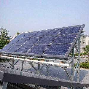
3 Engineering Disciplines Under This Hub
Utility-Scale Plain Solar Farm Racking System
Utility-Scale PV Mounting System for Plains & Flat Terrain Solar Farms
Standardized Flat-Ground PV Racking
Flat Ground PV Mounting & Level Site Solar Racking for Open-Field Projects
Plain Solar Farm Structure & Pile Foundation
Solar Pile Foundation & Farm Racking Structure for Level Farmland Sites
Why Plains / Flat Terrain projects are demanding
Plains and flat-terrain sites host the majority of the world’s utility-scale PV capacity because layout efficiency, piling productivity and O&M access are all at their best on level ground. The engineering challenge is different but real: long wind fetch, variable soil layers, flood levels and sheer scale make foundation selection and batch delivery the decisive cost items.
Site challenges we engineer around:
Challenge 01
Soil strata can change every few hundred meters, so a single pile design never fits the whole site
Challenge 02
High groundwater or seasonal perched water reduces effective embedment and complicates pile driving
Challenge 03
Flood-prone flats require column extension, scour checks and electrical routing above design water level
Challenge 04
Batch logistics: hundreds of thousands of piles and brackets must arrive in EPC sequence, not alphabetically
How to choose the right page
- If foundation cost and pile count dominate your business case, start with the utility-scale system page
- If you need repeatable kits and fast installation across similar blocks, start with the standardized racking page
- If your geotechnical report shows variable strata or high groundwater, start with the foundation page
Key technical parameters at a glance
Typical engineering envelopes for this segment; every project is recalculated against the destination-market code before fabrication:
| Parameter | Typical value / approach |
|---|---|
| Tilt envelope | 10-35 deg fixed-tilt window set by latitude and row-spacing study |
| Module interface | 30-35 mm framed modules, mid and end clamps per layout drawing |
| Fastening system | grade 8.8 bolts with flanged nuts and wedge-lock anti-loosening washers |
| Foundation options | ground screw, driven pile, rammed pile or ballast selected by soil report |
| Foundation mix | driven piles with a ballast option where soils refuse at depth |
| Row pitch | 8-12 m set by 3D shading study at 25-30 deg tilt |
Engineering requirements and design basis
- Tolerance strategy: pile head position, plumbness and height adjustment ranges matched to tracker or table tolerances
- Corrosion class selection by soil resistivity and coating life-to-first-maintenance target
- Geotech-to-pile mapping: each foundation type assigned to borehole zones, with pre-drilling options for refusal
- Pull-out and lateral tests on site before the design is frozen, not after
What this hub covers
- Utility-scale table and pile systems for large level plants
- Standardized racking for repeatable, fast-build flat-ground arrays
- Foundation selection where soil strata shift across the site
- Batch supply sequencing matched to EPC construction zones

Which configuration fits your site
Three supply configurations cover most plains / flat terrain procurement cases:
| Configuration | Structure and finish | Best for | Cost index |
|---|---|---|---|
| Economy line | Q235B main steel, hot-dip galvanized to ISO 1461 | GW-scale contiguous flat blocks | 1.0 (baseline) |
| Standard line | Q355B main members, 85 um+ zinc, pre-assembled brackets | typical plains / flat terrain tenders with standard code loads | +15-25% |
| Severe-site line | reinforced sections, duplex coating, sealed hardware | soft alluvial strata that drive pile-length steps | +35-50% |
Engineered solution
- Batch QA with mill certificates, coating thickness logs and per-batch torque verification
- Pile-driving guidance on site: crew training, template jigs and acceptance criteria agreed before mobilization
- Structure warranty and spare-part packaging sized for a 30-year service window
- One-package supply of piles plus structures, sequenced to EPC zones so driving crews never wait on steel
- Foundation decision table: driven piles for uniform soils, screw piles for refusal risk, ballast where penetration is prohibited
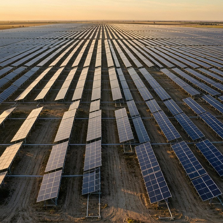
Industry benchmarks
The reference points below are anonymized industry benchmarks drawn from comparable public projects of this type. They are not claims about projects delivered by us, and no client, developer or operator is identified.
- A multi-gigawatt solar park in the Rajasthan desert, phased to roughly 2,245 MW where summer air temperatures approach 50 C. Racking for this class of site combines hot-dip galvanizing, sand-aware clamps and thermal-derating electrical design.
- A 1.5 GW desert plant in Saudi Arabia delivered on sandy terrain with driven piles and roughly 3.5 million modules. It proves that pile-and-structure supplied as one package can compress multi-hundred-MW schedules.
- A 2 GW plant in Abu Dhabi using around 3.5 million bifacial modules on single-axis trackers in high-dust desert conditions. It is a regional benchmark for tracker supply, yield guarantees and thermal-cycle fatigue design.
- A PV plant in Brandenburg, Germany on former military training land, a brownfield-reuse reference with cleared ground and low-disturbance foundations.
Installation method and site productivity
Ask how a structure installs before you compare its steel price. Our systems install with standard construction equipment – no proprietary tools, no site welding on the critical path. Piles are driven or screwed with industry-standard rigs and template jigs hold embedment tolerance; tables arrive preassembled in kits sequenced to your stacking plan; torque-controlled bolting with supplied torque values replaces welded connections; and rail adjustment ranges absorb the terrain error that grading leaves behind. We provide installation drawings, a step-by-step manual, torque and tolerance acceptance tables, and remote support during your install window. On request, an installation supervisor trains your crew on the first blocks.
Standards and compliance
- ASCE 7 / EN 1991 wind loads with site-specific terrain factors
- IEC 61215 / IEC 61730 for module interface compatibility
- EN 1090 or AISC execution classes for welded and bolted steelwork
- Hot-dip galvanizing to ISO 1461 with zinc mass specified by soil corrosivity
- ISO 9001 production quality management; batch traceability
- CE / EN 1090 documentation where destination markets require
Budget drivers and lead time
- Foundation choice typically moves total racking cost by 15-30 percent, more than rail gauge tuning ever will
- Steel price and hot-dip galvanizing weight are the two dominant variables; quotes should state both explicitly
- Pile length steps (2.0 / 2.5 / 3.0 m) are priced discretely – confirm refusal assumptions before contract
- Lead time: 4-8 weeks for standard fixed tables, 8-14 weeks for trackers, plus ocean freight to port of entry
- Quotations state steel grade, zinc mass and coating system explicitly; Incoterms and container plans are quoted to your destination port
Comparing supplier quotations
The cheapest structure per tonne is rarely the cheapest per megawatt installed. Compare at installed-cost level: pile count and driving productivity on your soils; preassembly ratio and site welding (should be zero); crane and crew days implied by the table design; tolerance adjustment range – wider ranges absorb terrain error and cut rework; packaging density and container count; and the commissioning support included. Then compare at ten-year level: coating life to first maintenance, fastener replacement expectations, spare parts availability commitments, and whether warranty claims reference measurable criteria. We quote with these lines visible so your finance team sees the same picture your engineers do.
Frequently asked questions
Why does flat terrain still need engineering?
What usually drives cost on a flat-terrain project?
Can you supply the whole flat-ground scope as one package?
What information do you need to keep a quotation valid?
What are your payment terms for first orders?
Ready to Start Your Plains / flat terrain Project?
What to include in your RFQ
- Site area, target capacity and expected block subdivision
- Geotechnical report or borehole data, plus groundwater level
- Design wind speed, terrain category and snow load
- Required delivery sequence and port of discharge
From RFQ to commissioning: how we work
A typical engagement runs in five gates: (1) RFQ review – we check drawings, geotech reports and load assumptions before quoting, and flag gaps that would move cost later; (2) proposal – structural basis, bill of quantities, foundation options and Incoterms stated side by side; (3) engineering freeze – pile tests or pre-drilling trials where soils demand them, shop drawings signed off by both engineering teams; (4) production – batch QA documents issued per lot, pre-shipment inspection open to your inspector or a third party; (5) delivery and install support – container plans matched to EPC sequence, installation manuals, torque tables and commissioning guidance. Each gate produces a document you can file; buyers tell us the discipline matters more than the brochures.
Send your geotechnical report and layout – we will return a foundation concept, pile count estimate and a costed supply package.
Quality, warranty and delivery
Every batch ships with mill certificates, coating-thickness logs and bolt records; welds follow EN 1090 or AISC execution classes. Structure warranty runs to 10 years with a 25-30 year service design life, and spare-part packages are documented so year-12 repairs do not depend on year-1 memory.
Control points from intake to handover
| Stage | What is checked | You receive |
|---|---|---|
| Material intake | steel grade and zinc mass verified against mill certificates | mill certificates and intake report |
| Production | weld quality, hole positioning and coating thickness sampled per batch | batch traceability sheet and QC photos |
| Pre-shipment | container loading plan, bolt-kit counts and packing list reviewed | packing list and loading photos |
| Site handover | installation walkthrough with torque values confirmed | installation manual, torque table and warranty letter |
| Site-specific check | pile-length verification against the geotech report before driving starts | project-specific method statement |
Documentation you receive
The paper trail matters as much as the steel. With each delivery you receive: mill test certificates traceable to heat numbers; galvanizing records per batch against ISO 1461 or your specified standard; dimensional inspection reports from pre-assembly jigs; bolt and hardware lot traceability; as-built drawings when site adaptations were made; and a warranty document that names covered load cases, service design life and claim procedures. O&M documentation includes a recommended inspection interval by environment class and a first-maintenance estimate in writing. Everything is indexed, so your asset register does not depend on one engineer’s memory.
Service life and maintenance planning
The economics of mounting systems are decided at year eight, not at signing. Galvanizing weight, fastener coating class and edge protection determine whether the year-eight inspection finds tight hardware or rust streaks. We publish expected first-maintenance intervals by environment class and back them with batch coating records, so warranty conversations start from data. For sites with special exposure – fertilizer plants, livestock ammonia, coastal spray, geothermal soils – we adjust coating and drainage detailing at design stage. Module replacement cycles are planned too: clamp designs allow individual module swap without cutting rails, which keeps mid-life rework fast and cheap.
