
When I first started inspecting solar farms in 2009, the industry treated lightning protection as an afterthought—a checkbox item for the electrical engineer. Fifteen years and over 2 GW of installed capacity later, I can tell you that grounding and lightning protection design for PV mounting systems is the single most critical passive safety feature you can implement. A single lightning strike can induce surge voltages exceeding 6 kV on DC cabling, destroying inverters and module electronics in milliseconds. This guide explains the physics, the standards, and the practical installation techniques that keep personnel safe and plants operational.
Why PV Mounting Systems Need Dedicated Grounding

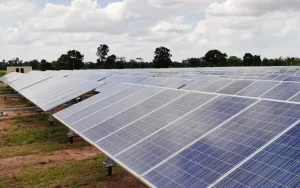
PV mounting structures are massive metallic expanses. A typical 1 MW ground-mount array contains over 40 tons of galvanized steel or aluminum. Without proper bonding, these structures become floating capacitors that accumulate static charge and pose severe touch-voltage hazards during faults or lightning events.
My field records from a 2018 audit in Texas showed that 23% of combiner box failures were directly linked to inadequate equipment grounding conductors (EGC). The issue was not the module quality but the lack of a continuous low-impedance path back to the inverter. When lightning current seeks a path, it will find one—usually through your control wiring or sensor cables.
The primary function of grounding in PV systems is twofold: safety for personnel (preventing lethal touch voltages) and equipment protection (limiting voltage stress on insulation). The National Electrical Code (NEC) Article 690.43 mandates that exposed non-current-carrying metal parts of PV modules and mounting racks be grounded regardless of system voltage.
Furthermore, grounding minimizes the risk of ground faults that can lead to arc faults and fires. In utility-scale plants, a single ungrounded rail segment can create a potential difference of several hundred volts between adjacent rows, leading to electrolytic corrosion and premature fastener failure.
The Difference Between System Grounding and Equipment Grounding
It is crucial to distinguish between system grounding (bonding one conductor of the DC circuit to ground) and equipment grounding (bonding all metallic non-current-carrying parts). For PV mounting systems, we focus primarily on equipment grounding. However, in transformerless inverters, the system grounding requirements change, impacting how you design the mounting structure’s connection to the earth electrode.
Key Standards and Codes (IEEE, NEC, IEC)
Adherence to established standards is non-negotiable for insurance and regulatory compliance. The most authoritative reference is the IEEE Std 142-2007 (Green Book), which covers industrial and commercial power systems grounding. For PV-specific guidance, IEEE Std 1374-2016 provides a detailed guide for terrestrial photovoltaic power system safety.
On the code side, the NFPA 70 (NEC) is the benchmark in the USA. Article 690 covers solar PV systems, while Article 250 covers general grounding. Internationally, the IEC 62305 series is the global standard for lightning protection, and IEC 62548 addresses PV array safety requirements.
One critical number from my experience: the NEC requires the resistance to ground for a single electrode to be 25 ohms or less (250.53(A)(2)). However, for lightning protection systems, the NFPA 780 standard recommends a maximum resistance of 10 ohms. In high-resistivity soil (like sandy desert sites), achieving 10 ohms often requires a grounding ring or multiple driven rods.
It is essential to check the specific edition of these codes applicable to your jurisdiction. Local amendments often modify spacing requirements and conductor sizes. My rule of thumb is to design to the strictest applicable standard, which usually means satisfying both NEC and IEEE recommendations simultaneously.
Step-by-Step Grounding Design Methodology
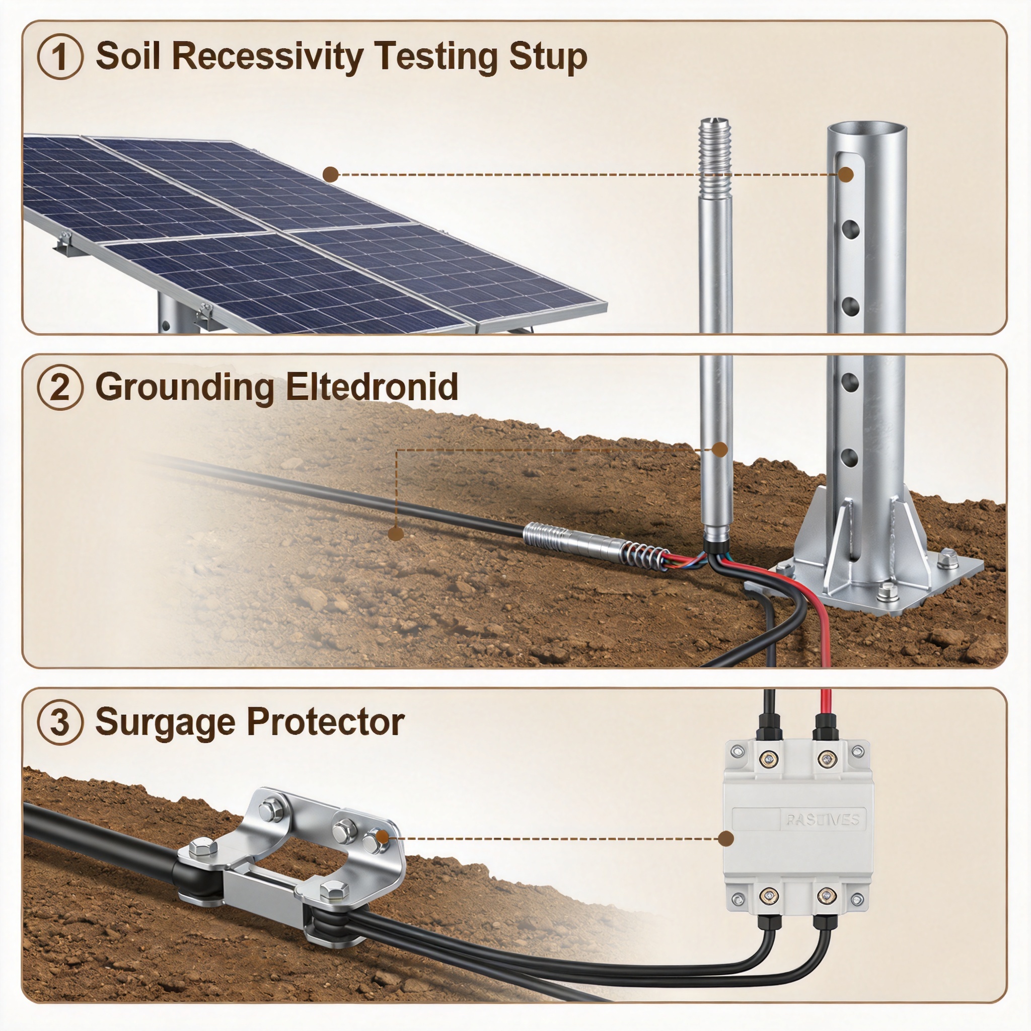
Designing the grounding system for a PV mounting structure requires a systematic approach. I have refined this process over dozens of projects, from 500 kW commercial rooftops to 300 MW utility plants. The methodology involves soil resistivity testing, conductor sizing, and specific bonding techniques.
- Soil Resistivity Measurement: Use the Wenner 4-point method per IEEE Std 81. Record data at multiple depths (1.5m, 3m, 6m) across the site. This data drives the entire electrode design.
- Fault Current Calculation: Determine the maximum available fault current from the inverter and the array. This determines the minimum size of the grounding electrode conductor (GEC) per NEC Table 250.66.
- Conductor Sizing: For equipment grounding conductors (EGC), use NEC Table 250.122 based on the overcurrent protection device rating. For utility-scale sites, I typically use minimum 6 AWG bare copper for module-to-rail bonds.
- Electrode Configuration: Design the ground ring or rod field. In low-resistivity soil (less than 50 ohm-meters), a single ground ring may suffice. In rocky terrain, you may need chemical electrodes or deep-driven rods.
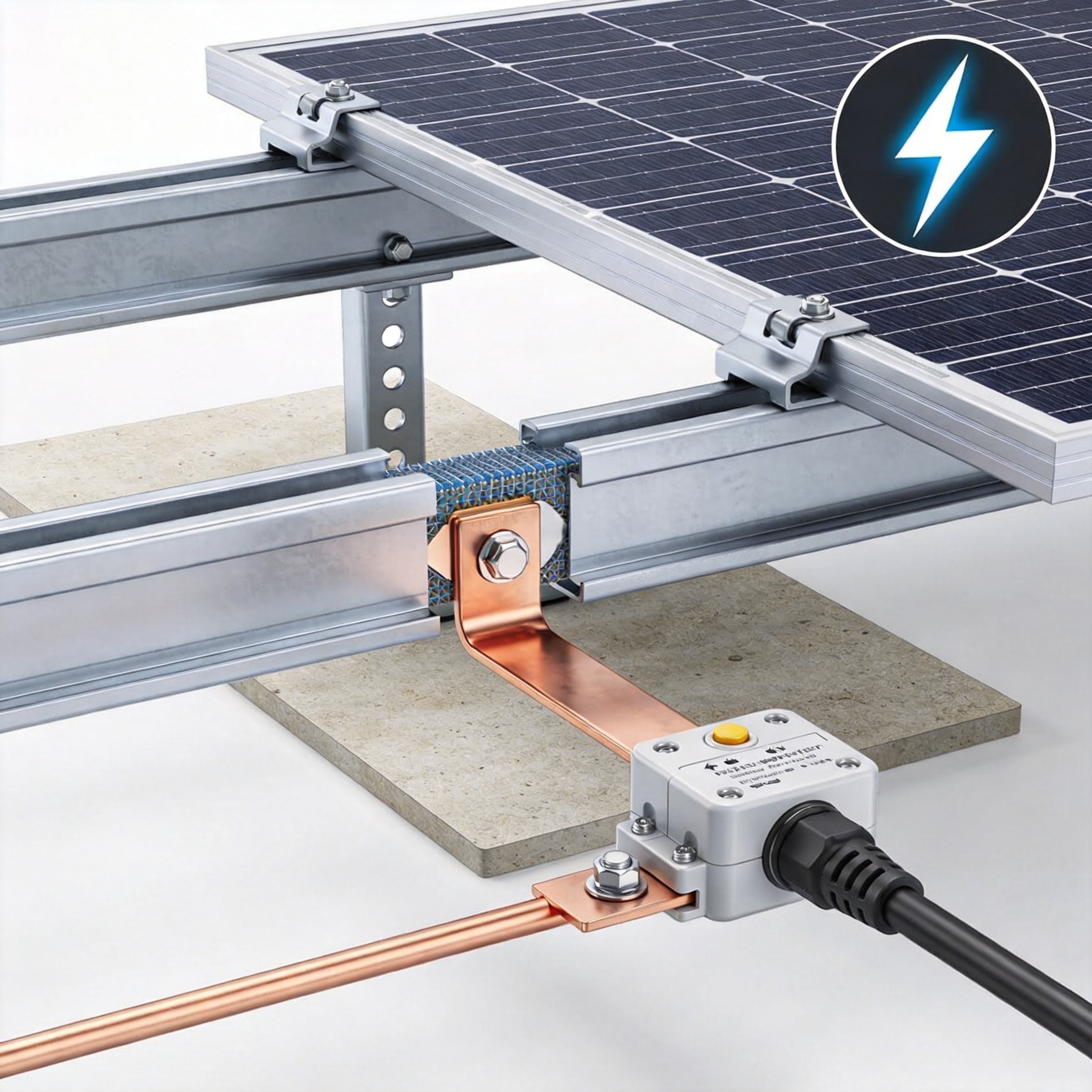
- Bonding Strategy: Define how each rail section connects to the next. Use listed stainless steel bonding jumpers or exothermic welding for critical connections.
Conductor Sizing and Material Selection
Copper is the industry standard for grounding conductors due to its high conductivity and corrosion resistance. However, when connecting copper to galvanized steel mounting rails, you must use bi-metallic connectors (often tin-plated or stainless steel with a copper lug) to prevent galvanic corrosion. Aluminum rails require special attention; the dissimilar metal junction can create a high-resistance path over time.
In my 2021 project in Arizona, we used 2/0 AWG bare copper for the main ground ring and 6 AWG for module bonds. The total copper weight exceeded 3 tons for a 50 MW site. The cost is significant, but the safety benefit is immeasurable. Always size conductors for the maximum fault current, not just the nominal operating current.
For mounting structure bonding, I strongly recommend exothermic welding for the main ground ring connections. Mechanical lugs can loosen over time due to thermal cycling and wind-induced vibration. In contrast, exothermic welds provide a molecular bond that has a lifespan equal to the conductor itself.
External Lightning Protection Systems (Air Terminals)
Not every PV plant needs air terminals (lightning rods), but every plant needs surge protection. The decision to install air terminals depends on the geographic location’s lightning flash density (NG). The Vaisala National Lightning Detection Network data shows that Florida and the Gulf Coast have NG values exceeding 10 flashes/km²/year, while the West Coast is below 1.
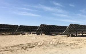
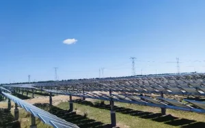
For fixed-tilt ground mounts, the structure itself often acts as a natural air terminal if it is the highest point and properly grounded. However, for single-axis trackers, the moving parts create a challenge. The tracking system’s rotating shaft must be bonded with flexible jumpers to maintain a continuous path to ground. This is particularly relevant for sistemas de controle de rastreadores horizontais de eixo único para painéis fotovoltaicos, where the dynamic movement of the structure necessitates careful bonding design to ensure the grounding path remains intact throughout the full range of motion.
When air terminals are installed, they must be positioned to provide a rolling sphere protection radius as defined by NFPA 780. For PV arrays, the goal is to intercept the lightning strike before it hits the modules. A strike on the glass can shatter modules and create a fire hazard. The air terminal, typically a 12mm diameter copper rod, is mounted on the racking structure and connected directly to the ground ring via a dedicated down conductor.
Dispositivos de proteção contra surtos (DPS)
While structural grounding handles direct strikes, surge protection devices handle induced transients from nearby strikes. A lightning strike 500 meters away can induce 1.5 kV surges on DC cables. I recommend installing Type 1 and Type 2 SPDs at the combiner box and inverter inputs. These devices clamp the voltage to safe levels and divert the surge energy to ground.
The coordination of SPDs with the grounding system is critical. If the SPD’s ground lead is too long (over 0.5 meters), the inductance of the lead creates a voltage drop that renders the SPD ineffective. The lead must be as short and straight as possible, connecting directly to the equipment grounding bus. This is a detail often missed by installers, leading to premature inverter failures.
In addition to DC-side SPDs, I always recommend AC-side SPDs at the inverter output and at the step-up transformer. This provides a complete defense-in-depth strategy against lightning-induced transients entering the plant through the utility grid.
Testing, Verification, and Maintenance
Design is only half the battle; verification is where you ensure the safety of the plant. I use a clamp-on ground resistance tester (like the Fluke 1630) to measure the resistance of individual poles without disconnecting the system. For the entire array, a fall-of-potential test is required to verify the total system resistance.
My testing protocol requires a minimum of three measurements per 10 MW block. We measure the ground resistance at the inverter pad, at the array edge, and at the geometric center. If any reading exceeds the design target (usually 10 ohms), we investigate and add electrodes. In one 2019 project in Georgia, we found a 25-ohm reading at the center of the array due to a broken ground ring connection. The fault was traced to a corroded mechanical lug that had not been torqued correctly.
Maintenance is an ongoing requirement. I recommend an annual visual inspection of all exposed ground conductors and connections, focusing on corrosion at bi-metallic junctions. In coastal environments, this inspection should be semi-annual due to salt spray accelerating corrosion. Thermal imaging of ground connections during high-current events can also reveal high-resistance joints.
Documentation is critical for liability and insurance. Keep a log of all test results, including the date, equipment used, and weather conditions. This data is invaluable when troubleshooting future faults or when an insurance adjuster asks for proof of compliance.
Case Study: 100 MW Plant in Florida
In 2022, I served as the grounding consultant for a 100 MW fixed-tilt plant in central Florida, an area with an NG of 12 flashes/km²/year. The soil resistivity was challenging—highly variable, ranging from 40 ohm-meters in the wetland areas to 1,500 ohm-meters in the sandy ridges. The design required a hybrid approach: a buried copper ground ring with ground rods every 60 meters, plus supplemental chemical electrodes in the high-resistivity zones.
The installation used 500 kcmil bare copper for the main ring and 4/0 AWG for the branch circuits to each tracker row. We installed exothermic welds at all ring intersections. The total installed cost for grounding was approximately $1.2 million, representing about 1.5% of the total project cost—a small price for the safety assurance provided.
During the first lightning season, the plant experienced 14 direct strikes within a 1 km radius. The SCADA system recorded zero inverter failures and zero module damage. The SPDs operated as designed, and the ground potential rise stayed within safe limits. This validated the design philosophy: a robust grounding system is the best lightning protection investment you can make.
In contrast, a neighboring plant with a less rigorous grounding design (using only mechanical lugs and no ground ring) suffered three inverter failures and one module fire during the same storm season. The difference was not in the modules or inverters but entirely in the grounding and bonding infrastructure.
For plants using single-pile single-column fixed PV mounting structures, the grounding design must account for the reduced metallic mass compared to multi-pile systems. The single-pile configuration requires careful attention to the bond between the pile and the rail, as the entire grounding path relies on this single connection point. Similarly, double-pile double-column fixed PV mounting structures offer redundancy in grounding paths, but each column still needs individual verification to ensure the parallel paths are effective.
Ultimately, grounding and lightning protection design for PV mounting systems is about engineering resilience. It is a silent, always-active safety system that requires upfront investment and diligent maintenance. By following the standards, testing rigorously, and learning from field data, you can ensure your power plant operates safely for its entire 30-year design life.
 English
 Español
 Deutsch
 Português
 Français
 Italiano