





What This Group Covers
That changes the racking decision. Layout has to work around process infrastructure, foundations have to coexist with buried services, and the owner usually wants to expand in phases rather than build once.
- Ground-mount racking for industrial captive plants sized 1 to 20 MW
- Sites where the array must route around existing pipe racks, conveyors, roads and buried services
- Heavy-industry environments with dust, vibration and aggressive atmospheric corrosivity
- Water utilities and treatment works, where structures coexist with tanks, clarifiers and process buildings
- Phased expansion: designing for a second and third stage without relocating stage one
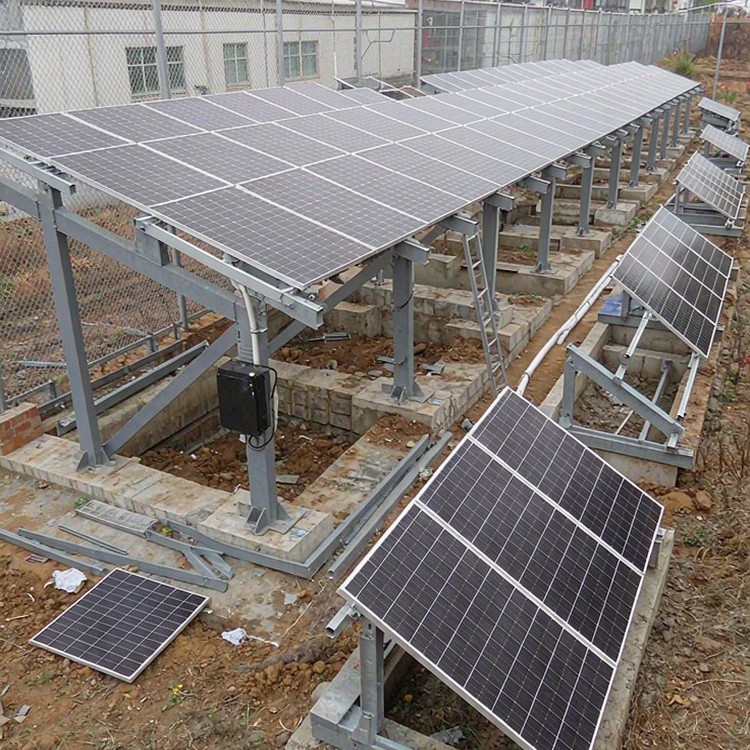
Three Configurations to Start From
Three supply configurations cover most industrial captive cases:
Standard line
Q355B steel, hot-dip galvanized to ISO 1461, driven or screw piles. Best for: Open industrial land with documented services. Relative cost: 1.0 (baseline).
Low-impact line
Screw piles or ballasted bases, ZAM steel, no excavation required. Best for: Live sites where excavation and vibration are prohibited. Relative cost: +12 to +22%.
Aggressive-atmosphere line
Heavier zinc mass or duplex coating, sealed hardware, drainage detailing. Best for: Stack emissions, dust or chemical fallout on site. Relative cost: +25 to +45%.
Why industrial captive projects are demanding
An industrial site is the least forgiving place to build a solar plant. The land is already in use, the underground is full of services nobody documented properly, and the operating plant cannot stop while you install next to it. Every design decision has to survive contact with an active industrial environment.
- Buried services, cable ducts and drainage run through the only available array area, and the first excavation often finds something the drawings missed
- Process dust, stack emissions and vibration shorten the life of coatings and fasteners well below clean-air assumptions
- The plant’s load profile rarely matches solar generation, so the array is sized for self-consumption rather than maximum energy, which changes the optimal layout
- Phased construction means the first stage must be designed so stage two can be built without dismantling or re-working stage one
- Site access, hot-work permits and shutdown windows constrain installation far more than on a greenfield site
Engineering Requirements
We treat the operating plant as a design constraint, not a construction inconvenience. These are the checks that decide whether a captive plant builds to schedule.
- Service detection and clearance mapping: every buried duct, pipe and cable route surveyed and excluded from foundation positions
- Corrosion class selection against real stack emissions and dust chemistry, not generic inland-industrial defaults
- Foundation types that can be installed without vibration or excavation near live plant, such as screw piles or ballasted bases
- Phasing design: foundation and cable routes laid out so later stages connect at pre-installed tie-in points
- Clearance and access envelopes maintained for maintenance vehicles, fire access roads and crane lifting paths
- Structural design against the site’s measured wind exposure, including shelter or acceleration effects from adjacent large buildings
Selection guidance: fix the service clearance map and the phasing plan before the layout, because both are expensive to change once foundations are in the ground.
Key Parameters
| Parameter | Typical specification |
|---|---|
| Deployment | Ground-mount fixed-tilt or tracker, phased by process area |
| Capacity band | 1-20 MW, typically built in 2-6 MW stages |
| Foundation options | Screw piles, ballasted bases or driven piles selected by service clearance and vibration limits |
| Corrosion class | C3 to C4 typical on heavy-industry sites; C5 where stack emissions are aggressive |
| Wind design | Site-specific terrain factors including acceleration between large buildings |
| Service clearance | 1.5-3 m horizontal offsets from buried services, verified by survey |
| Phasing | Tie-in points and spare foundation positions reserved for later stages |
| Access | Fire access roads and maintenance vehicle turning radii preserved through the array |
How We Deliver It
- Foundation selection driven by what is under the ground: screw piles where excavation is impossible, ballasted bases where vibration is prohibited, driven piles where soils allow and access permits
- Corrosion system stepped for real emissions data, with duplex coating or higher zinc mass where stack fallout is aggressive
- Layout produced from a surveyed service map, so no foundation position is left to discovery during construction
- Phasing built into the drawing set: reserved tie-in points, matched rail families and continuation details for stages two and three
- Installation sequencing planned around shutdown windows and permit constraints rather than a theoretical construction calendar
- Reinforced structures where the array sits in a shelter or acceleration zone created by adjacent plant buildings
Standards and Compliance
- ASCE 7 / EN 1991 / AS-NZS 1170 wind load cases with site-specific terrain categories
- IEC 62727 tracker structural requirements where tracking structures are in scope
- EN 1090-2 or AISC 360 fabrication and execution class documentation
- ISO 1461 hot-dip galvanizing, ISO 9223 corrosivity classification driving zinc mass
- ISO 9001:2015 quality system, ISO 14001 environmental management on request
- Third-party aeroelastic wind tunnel study available for large-format modules
Quality Assurance
Batch documentation is issued per lot: mill certificates traceable to heat numbers, galvanizing records with measured coating thickness, dimensional inspection reports from pre-assembly jigs and hardware lot traceability. Warranty covers named load cases and environmental exposure classes, so claims are settled against data rather than negotiation.
Installation and Site Productivity
Installation speed is designed in, not improvised on site. Pre-assembly ratios are set so the maximum amount of work happens in the factory; parts are kitted and labelled by build sequence so crews never search for components; connection details avoid site welding and minimise the number of distinct fastener types; and adjustment ranges at the interface tolerate the position error that foundation installation inevitably produces. We supply an installation manual with crew sizing, daily output targets and acceptance criteria.
Documentation You Receive
Documentation is built for audits, not decoration: structural calculation notes stating load cases and standards used; foundation design basis mapped to your geotechnical report; material certificates for steel and fasteners; galvanizing certificates with measured coating thickness per batch; assembly drawings with torque tables; and packing documentation matched to container manifests. For financed projects we add lender-format compliance statements; for public tenders we respond to documentation schedules line by line.
Cost and Commercial Considerations
- Service detection and clearance survey is a small line item that prevents the largest category of site delay
- Low-vibration foundation methods add 12-22 percent on structure but avoid production shutdown costs that dwarf the premium
- Coating upgrades for aggressive atmospheres add 8-15 percent to structure cost and typically double the interval to first maintenance
- Phasing provisions – reserved tie-in points and continuation details – cost under 3 percent if designed in and far more if retrofitted
- Lead time: 4-8 weeks for standard fixed structures, plus survey and permit time that is usually on the critical path
Reference Benchmarks
- A 12 MW captive plant for a cement works in Vietnam, built in three stages with fixed-tilt arrays routed around conveyor lines and a raw-mill dust plume.
- A 6 MW self-consumption plant at a steel rolling mill in Turkey, using low-vibration screw foundations within 15 m of live production halls.
- A 4 MW ground-mount array at a mine site in Chile, duplex-coated for high dust and chloride exposure with a 25-year structural design life.
- An 8 MW phased installation at an automotive plant in Mexico, where stage one foundations and cable routes were reserved for a stage two that followed 18 months later.
Service Life and Maintenance Planning
Plan maintenance around measurable triggers, not calendar guesses: annual visual inspection of fastener torque samples, coating condition at cut edges and ground-contact zones; a detailed inspection after the first extreme weather year; and re-torque verification after the first thermal cycle on long runs. We supply the inspection checklist and acceptance criteria with the installation manual.
How We Control Delivery
| Stage | What we do | What you receive |
|---|---|---|
| Service survey | buried ducts, pipes and cables verified across the array footprint | annotated clearance map and exclusion zones |
| Layout freeze | foundation positions cleared against the service map and the phasing plan | layout drawing with reserved stage-two tie-ins |
| Material intake | steel grade, coating system and fastener class verified against the specification | mill certificates and coating thickness records |
| Pre-shipment | kit labelling by phase and by array block checked against the build sequence | packing list matched to phase and block |
| Site handover | foundation positions, torque values and reserved tie-in points confirmed | installation manual, as-built drawing and warranty letter |
Send the site layout and any service drawings – we will return a phased structure plan, foundation options and a costed supply package.
Guides in This Group
Ground-Mount Racking for Industrial Captive Power
Self-consumption arrays sized to the plant load: layout, phasing and foundation strategy.
Solar Racking for Steel, Cement & Heavy Industry
Dust, vibration and aggressive atmospheres: coating selection and low-impact foundations.
Solar Racking for Water Utilities & Treatment Plants
Arrays that coexist with tanks, clarifiers and process buildings on live treatment works.
Related Application Directories
This scale band is often combined with the following application groups, which cover terrain, land type and site conditions.
Frequently Asked Questions
Can you design around buried services we have not fully mapped?
How do you avoid disrupting production during installation?
Our site has heavy dust and stack fallout. What changes?
Can you build it in phases as our load grows?
What if we later add a battery or expand the array?
What We Need to Quote
- Site layout with process infrastructure, roads and any known buried service routes
- Target capacity per phase and the intended build sequence
- Geotechnical information and any vibration or excavation restrictions on the site
- Design wind speed, terrain category and the atmospheric environment around the array area
Talk to a Structure Engineer
Send your site data, target capacity and construction programme, and our engineers will return a structure concept, a quantity estimate and a costed supply package.
