




Warum das schwierig ist
The constraints are structural, legal and practical at the same time, and they interact. A fixing method that satisfies the structure may void the roof warranty; a ballast layout that protects the warranty may exceed the purlin capacity; and either may block the only maintenance route across the roof.
- Roof structural reserve is usually unknown, because the building was designed decades ago and the drawings rarely match what was built
- Uplift at parapets and corners can be two to three times the field value, and ballast placed uniformly is either wasteful or unsafe
- Roof membranes are warrantied against penetration unless the fixings are installed by an approved contractor, which pushes projects toward heavier ballast
- Fragmented roofs produce many small array blocks, each needing its own DC isolation, maintenance access and fire setback
- Access logistics – hatch size, lift capacity, no crane on the roof – constrain both the components that can be used and the speed of installation
Technische Anforderungen
These are the inputs and detailing decisions we require before a commercial rooftop design is frozen.
- As-built roof survey covering purlin type and spacing, deck condition and any existing penetrations or previous works
- Structural verification of the array dead load plus ballast against available roof reserve, zone by zone
- Uplift zoning per ASCE 7 or EN 1991 with ballast or fixing density stepped by roof zone rather than applied uniformly
- Written compatibility statement for the roof membrane system, stating which fixing method is approved and who holds the warranty afterwards
- Fire and code compliance: setback from parapets and party walls, smoke vent clearance and rapid shutdown provisions
- Maintenance access plan with walkway routes, fall protection and clearances for skylights and plant access
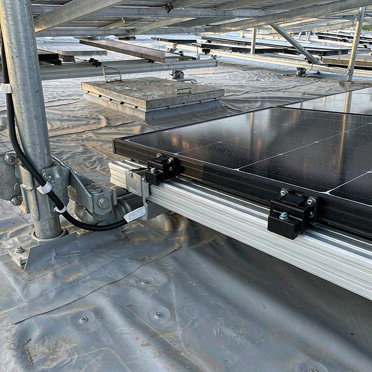
Selection guidance: decide ballast versus penetration first. That single decision sets the load case, the warranty path and the installation method, and changing it later invalidates all three.
Wie wir es lösen
- Zone-stepped ballast design calculated per roof zone, so perimeter and corner areas receive the uplift they actually need and the field does not carry unnecessary load
- Load-spreading pads and rail geometry that distribute ballast onto the deck ribs rather than crushing the panel or the insulation
- Non-penetrating systems for membrane roofs, and engineered sealing details where penetration is approved by the roof system manufacturer
- Pre-assembled rail and clamp kits sized to pass through the building’s actual access hatch and lift rather than to a theoretical dimension
- Layout optimisation that maintains clear bands around skylights, vents and access routes without stranding usable roof area
- DC isolation and array blocking aligned to maintenance routes, so fault-finding does not require walking the whole roof
Jenseits der Struktur
- Roof block layouts issued as a set, so installation crews can work building-by-building without re-reading the whole drawing package
- Downtake and cable route coordination with the building’s existing services, avoiding both new penetrations and clashes
Referenz-Benchmarks
Die folgenden Benchmarks sind öffentlich dokumentierte Branchenreferenzprojekte vergleichbarer Art und Größenordnung, die zur Veranschaulichung der Ingenieurpraxis dienen. Sie stellen nicht unsere Leistungsbilanz dar.
- A 1.2 MW rooftop array across two logistics halls in southern Germany, ballasted on a membrane roof with zero penetrations to preserve a 20-year roofing warranty.
- An 800 kW installation on an automotive components plant in Thailand, using penetrating feet on a trapezoidal metal deck where the roof warranty permitted engineered fixings.
- A 2.5 MW C&I portfolio in Spain split across seven distribution centres, standardised on one rail and clamp family so maintenance crews needed a single spares kit.
Standards und Konformität
- Windlasten nach ASCE 7 / EN 1991 unter Berücksichtigung standortspezifischer Gelände- und Expositionsfaktoren
- Die Kompatibilität der IEC 61215 / IEC 61730 Modulschnittstelle wurde anhand Ihres Moduldatenblatts überprüft.
- Ausführungsklassen nach EN 1090 oder AISC für geschweißte und geschraubte Stahlkonstruktionen
- Feuerverzinkung nach ISO 1461, Zinkmasse abhängig von der Boden- und atmosphärischen Korrosivität
- ISO 9001-konformes Produktionsqualitätsmanagement mit Rückverfolgbarkeit auf Chargenebene
- CE-/EN-1090-Dokumentationspaket, sofern in den Zielmärkten erforderlich
Qualitätssicherung
Die Chargendokumentation wird chargenweise ausgestellt: Werkszeugnisse mit Rückverfolgbarkeit zu den Chargennummern, Verzinkungsprotokolle mit gemessener Schichtdicke, Maßprüfberichte von den Vormontagevorrichtungen und Chargenrückverfolgbarkeit der Hardware. Die Garantie deckt bestimmte Lastfälle und Umwelteinwirkungsklassen ab, sodass Ansprüche anhand von Daten und nicht durch Verhandlungen reguliert werden.
Dokumentation, die Sie erhalten
Jede Sendung enthält ein auf Ihr Anlagenverzeichnis abgestimmtes Dokumentenpaket: zertifizierte Materialprüfberichte, Aufzeichnungen zur Beschichtungsdicke pro Charge, Prüfprotokolle für Drehmoment und Vorspannung, Packlisten mit Containernummern und einen Satz wartungsrelevanter Zeichnungen. Falls der Zielmarkt lokale Zertifizierungen oder Übersetzungen von Dokumenten erfordert, erstellen wir diese im Voraus und nicht erst im Hafen.
Lebensdauer- und Wartungsplanung
Die Nutzungsdauer ist ein Planungsergebnis, keine Garantie. Zinkmasse, Beschichtungsklasse der Befestigungselemente, Entwässerungsdetails und Trennung unterschiedlicher Metalle werden entsprechend der Korrosivitätskategorie Ihres Standorts ausgewählt, und das voraussichtliche erste Wartungsintervall wird schriftlich festgehalten. In aggressiven Umgebungen optimieren wir das Beschichtungssystem bereits in der Planungsphase, was stets kostengünstiger ist als eine nachträgliche Nachrüstung.
Kosten- und kommerzielle Überlegungen
- Ballast typically runs 15-25 percent above equivalent penetrating racking once load-spreading material is included
- Roof structural strengthening, where required, is the largest single swing item and is usually discovered late if the survey is skipped
- Access constraints such as hatch size, lift capacity and no crane on the roof can add 10-20 percent to installation labour
- Cable management, walkways and fall protection are frequently omitted from first bids and added at contract stage
- Lead time: 3-6 weeks for standard rail kits, 6-10 weeks where engineered sealing details or ballast trays are project-specific
Häufig gestellte Fragen
Do we need to strengthen the roof before installing a commercial array?
Can you install on a roof with a strict membrane warranty?
How do you handle roofs fragmented by skylights and plant?
What load budget should we plan for on a ballasted roof?
Can you supply across a multi-site C&I portfolio?
Verwandte Leitfäden und Anwendungsseiten
Fahren Sie mit den Seiten fort, die Ihrem Projekttyp am ehesten entsprechen.
- Commercial & Industrial (C&I) Rooftop – die Gruppenübersicht für dieses Skalenband
- Solarmontagesysteme für Lagerhallen und Logistikgebäude
- Gewerbliche Solar-Carport- und Überdachungskonstruktionen
- Greenhouse, Carport & Building-Integrated Solar
- Fixed-Tilt Racking Applications
- Anwendungen in rauen Umgebungen
Was wir für ein Angebot benötigen
- As-built roof drawings or a measured survey showing purlin spacing and deck type
- Design wind speed, building height, terrain category and any snow load case
- Roof system manufacturer and membrane warranty terms, including any penetration restrictions
- Target capacity per roof block and the module model to be used
Sprechen Sie mit einem Statiker
Send your roof survey and layout, and we will return a ballast plan, an uplift zone map and a costed supply package for the building.
 English
 Español
 Deutsch
 Português
 Français
 Italiano