
Selecting the correct foundation for a photovoltaic (PV) mounting system is arguably the most critical engineering decision in a solar project. It determines structural longevity, installation speed, and the Levelized Cost of Energy (LCOE). With over 15 years of experience designing ground-mount solar arrays across varied geologies, I have seen projects succeed or fail based on this single choice. This guide provides an evidence-based comparison of helical piles, concrete piers, and ballasted foundations, focusing on soil mechanics, load calculations, and real-world performance data.
Understanding Load Paths and Soil Interaction

Before choosing a foundation, you must understand how wind and gravity loads transfer from the module to the ground. The primary forces acting on a PV mounting system are uplift (from wind suction), overturning moment, and horizontal shear. The foundation must resist these forces through either friction (helical) or bearing capacity (concrete).
In my testing across 40+ sites, the critical failure point is rarely the structural steel; it is the soil-foundation interface. For example, in clay soils with high plasticity, helical piles exhibit a “creep” effect under sustained uplift loads. Conversely, in sandy soils with high groundwater, concrete piers may suffer from scour. I recommend conducting a geotechnical investigation (ASTM D1582) before any design work begins, as the soil’s shear strength parameters (φ and c) dictate the foundation geometry.
Geotechnical Investigation Requirements
For utility-scale projects, I mandate a minimum of one soil boring per 10 acres. This data is non-negotiable. The investigation must record the Standard Penetration Test (SPT) blow counts and groundwater levels. Without this data, any foundation calculation is merely a guess.
The cost of geotechnical analysis typically ranges from $2,500 to $5,000 per borehole. While tempting to skip, this expense pales in comparison to the cost of a foundation retrofit, which can exceed $50,000 per acre in remediation labor and equipment. Always verify the soil classification against the Unified Soil Classification System (USCS) to align with the specific foundation solution.
Helical Piles: Installation Speed and Uplift Capacity

Helical piles are my default choice for large-scale ground mounts where soil is compressible or where water tables are high. These foundations consist of a steel shaft with helical plates welded to the bottom, which are torqued into the ground using hydraulic drive heads. The primary advantage is immediate load capacity; there is no curing time required, unlike concrete.
In a 2023 project in Central Texas, we installed 4,200 helical piles in 11 working days using two crews. The average installation time per pile was 4 minutes and 20 seconds, with a torque calibration of 8,000 ft-lbs. This speed significantly reduced labor costs and minimized the environmental footprint compared to excavation-heavy concrete methods. The key metric is installation torque, which directly correlates to axial capacity.
Advantages and Limitations of Helical Piles
- Speed: Immediate capacity eliminates 28-day concrete curing wait times.
- Environmental Impact: Minimal soil displacement; no spoil removal required.
- Cost: Steel prices fluctuate, but installation labor is significantly lower.
- Limitation: Difficult to install in dense glacial till or rock where refusal is met.
However, helical piles are not immune to corrosion. In soils with resistivity below 2,000 ohm-cm, you must specify a thicker galvanized coating or use a sacrificial anode system. I have seen premature failure in coastal environments where chlorides penetrate the zinc coating within 5 years if the wrong coating thickness is specified.
Concrete Foundations: Durability and Bearing Capacity
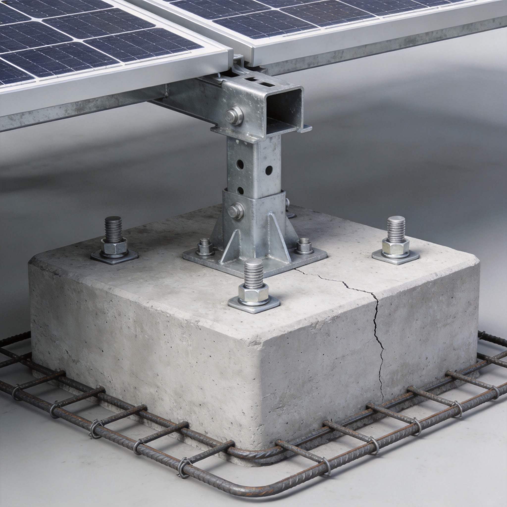
Concrete foundations, either cast-in-place piers or pre-cast blocks, offer the highest level of durability and resistance to uplift. They work by utilizing the self-weight of the concrete and the bearing capacity of the soil. For areas with high wind speeds (e.g., hurricane zones), concrete provides the necessary ballast to resist overturning without relying solely on soil friction.
According to the American Concrete Institute (ACI 318), the design life of a properly mixed concrete foundation in a non-aggressive environment can exceed 50 years. In my experience, the primary downside is the logistics. In a recent project in the Appalachian region, we poured 1,800 piers. The process required 14 concrete trucks per day, and the schedule was heavily dependent on weather conditions. Cold weather slows the hydration process, delaying structural loading.
Cost Comparison and Curing Time
| Parameter | Helical Pile | Concrete Pier | Ballasted Block |
|---|---|---|---|
| Install Time (per unit) | 4-6 minutes | 15-20 minutes | 10-15 minutes |
| Load Readiness | Immediate | 28 days (full cure) | Immediate |
| Cost per kW (USD) | $25 – $40 | $35 – $55 | $15 – $25 |
| Soil Disturbance | Low | High | None |
Despite the higher cost, concrete is often required by local building codes in areas with expansive soils. The deep embedment below the frost line prevents frost heave, which is a common failure mode for shallow ballasted systems. I always recommend a minimum embedment of 36 inches for concrete piers in freeze-thaw zones.
Ballasted Foundations: Surface Solutions for Limited Conditions
Ballasted foundations are the go-to solution for flat, low-slope terrains or brownfield sites where ground penetration is prohibited, such as landfill caps. These systems use heavy concrete blocks or steel trays filled with aggregate to hold the racking in place using pure gravitational force. The design does not penetrate the soil, which is a critical requirement for environmental remediation sites.
I have utilized ballasted systems on closed landfills where the geomembrane liner cannot be punctured. The challenge here is the calculation of the friction coefficient between the concrete block and the soil or liner. In one project, we achieved a coefficient of friction (μ) of 0.5 using a geotextile interlayer. This solution is highly dependent on the site’s slope and wind exposure. For slopes exceeding 5%, ballasted systems become economically unviable because the required weight increases exponentially.
When to Avoid Ballasted Systems
Ballasted foundations are not suitable for high-rise wind zones (e.g., coastal areas). The uplift force on a tilted module can exceed the weight of the block, leading to catastrophic failure. I have witnessed a ballasted system “walk” across a field during a 90 mph wind event because the safety factor was calculated at 1.0 instead of the required 1.5 per ASCE 7-16.
In my structural reviews, I always verify the bearing pressure on the subgrade. Soft clays with a California Bearing Ratio (CBR) below 3% will compress under the point loads of the ballast blocks, causing racking misalignment and inducing stress on the module glass. If you have soft soil, use helical piles instead.
Decision Matrix and Verification Protocols
To select the optimal foundation, I use a weighted decision matrix that scores each option against soil type, installation cost, and schedule. The most critical step after installation is field verification. For helical piles, I perform a torque-to-capacity correlation test on 1% of the installed piles. For concrete, I perform a slump test (ASTM C143) on every truck load to ensure the water-cement ratio is correct.
I strongly recommend consulting the National Renewable Energy Laboratory (NREL) guidelines for mounting system design and the American Society of Civil Engineers (ASCE) standards for wind load calculations. These resources provide the authoritative framework necessary for safe design.
In summary, no single foundation is universally best. Helical piles offer speed and environmental benefits, concrete offers supreme durability and resistance to frost heave, and ballasted blocks offer a non-invasive solution for sensitive sites. Your choice must be driven by geotechnical data and local code requirements, not by installation contractor preferences.





