
A practical framework for utility‑scale and ground‑mounted projects – from site data to lifetime economics.
Core principle: Select the mounting system after you have evaluated the site, energy objectives, and lifecycle cost model – not before.
Kingshore New Resources provides engineered solar mounting solutions that balance structural integrity, construction speed, and long-term ROI. This guide walks you through a disciplined selection process, ensuring every decision is driven by project‑specific data rather than generic assumptions.
1. Define Your Project Objective
Start by clarifying what matters most – this prevents comparing structures only by upfront price or steel weight. Consider:
- Energy yield – annual output and hourly profile (especially morning/evening generation value).
- Capital cost & schedule – budget, installation timeline, and available labor/equipment.
- Land use – row spacing, grading limits, and future site utilisation.
- Operations & maintenance – complexity, technician skills, and target availability.
- Grid constraints – export limits, tariff windows, curtailment exposure, and financial model.
Agree on the decision criteria before freezing the design – energy, structural, and commercial trade‑offs become much more expensive to change later.
2. Match the Structure Type to the Use Case
Different systems solve different problems. Shortlist the technology that best fits your site rather than forcing a single solution across all projects.
Fixed‑Tilt & Seasonal‑Tilt Systems
Mechanical simplicity and predictable O&M. Ideal for CAPEX‑sensitive projects, tight construction windows, or sites where tracking adds limited value. Seasonal‑tilt allows periodic angle adjustments without motors or controls.
Horizontal Single‑Axis Trackers (1P / 2P)
Trackers rotate modules throughout the day, extending productive hours. Well‑suited for utility‑scale projects where the extra yield, better DC utilisation, and shoulder‑hour generation justify the added mechanics and controls. Evaluate both 1P and 2P formats against module layout, terrain, wind design, installation method, and O&M strategy.
Tilted Trackers & Specialised Structures
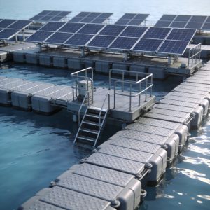
Tilted single‑axis trackers may be relevant at certain latitudes or where diffuse light and seasonal geometry support an inclined plane. Agrivoltaic, carport, and floating structures serve dual‑use land objectives – here clearance, access, safety, and secondary use become primary design inputs.
Quick Reference Table
| System | Best Suited For | Primary Value | Validate Carefully |
|---|---|---|---|
| Fixed / Seasonal Tilt | Simple layouts, CAPEX‑focused projects | Mechanical simplicity, predictable O&M | Energy trade‑off, row spacing, optimal tilt |
| 1P / 2P Single‑Axis Tracker | Utility‑scale projects prioritising lifetime energy value | Longer generation window, adaptive operation | Wind, terrain, controls, stow, O&M capability |
| Tilted Single‑Axis Tracker | Sites where modelling supports an inclined plane | Tracking with site‑specific tilt strategy | Solar resource, latitude, wind, structural complexity |
| Agrivoltaic / Carport / Floating | Dual‑use land, agriculture, or parking | Additional value from the same area | Clearance, access, safety, end‑user requirements |
3. Let Site Data Drive the Design
Reliable design starts with verified site information. Preliminary assumptions are fine for bidding, but they should not become the final basis without validation.
- Geotechnical investigation – soil layers, bearing capacity, pull‑out resistance, groundwater, rock depth.
- Topographic survey – slopes, undulations, cut‑and‑fill needs, tracker articulation limits.
- Hydrology & drainage – flood levels, runoff paths, erosion risk, foundation exposure.
- Site access – transport routes, lifting methods, equipment movement, module handling.
- Environmental exposure – coastal salinity, industrial pollutants, humidity, temperature range, dust.
These inputs determine pile length, member sizing, deflection limits, coating systems, row layout, and installation practicality. Missing data usually reappears as variations, delays, or rework.
4. Engineer for Wind, Terrain & Environmental Loads
Wind is one of the most critical design inputs. The basis should reflect site‑specific wind speed, terrain category, topography, structure height, module geometry, and applicable codes. For trackers, also review stow strategy, control response, drive‑line behaviour, torsional effects, and acceptable deflection.
The goal is not to maximise steel weight – it is to achieve compliant strength, stiffness, and stability with efficient material use. A credible supplier (like Kingshore New Resources) will clearly explain the assumptions, load path, analysis method, and safety factors behind the design.
5. Choose the Foundation Only After Ground Testing
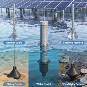
Foundation selection must follow geotechnical investigation and field trials. Driven steel piles are efficient on many sites, while ground screws, bored concrete piles, rock anchors, or ballasted solutions may be better where refusal, shallow rock, weak soils, or environmental constraints exist.
- Confirm compression, lateral, and pull‑out capacity through an agreed test programme.
- Check installation tolerances and how the superstructure accommodates unavoidable deviations.
- Evaluate corrosion at and below ground level, including soil chemistry effects.
- Plan for refusal, pre‑drilling, remediation, and quality documentation before mass installation.
A foundation that looks cheap on paper can become costly if it requires unplanned drilling, concrete work, rework, or specialised equipment during execution.
6. Check Material Protection & Manufacturing Quality
Solar structures operate outdoors for decades – corrosion protection and manufacturing consistency must be treated as design requirements, not procurement details. The coating system should match site exposure, and fasteners, interfaces, and repair procedures for damaged coatings should be included.
- Material certificates, grade traceability, and controlled incoming inspection.
- Galvanising or coating specification appropriate to environmental exposure.
- Dimensional accuracy, hole alignment, and repeatable fabrication tolerances.
- Welding, punching, forming, and surface‑treatment quality controls.
- Inspection records and identification that remain traceable through delivery.
Precise manufacturing speeds installation because members, fasteners, and module interfaces fit as designed – reducing field modifications that can compromise coating and documentation.
7. Design for Construction & Operations
A good structure is efficient to install and straightforward to maintain. Review the system with construction and O&M teams – not only design and procurement.
- Part count, pre‑assembly options, packaging sequence, and site logistics.
- Tooling, lifting needs, torque control, and installation training.
- Tolerance management, inspection points, and commissioning documentation.
- Safe access for vegetation control, cleaning, inspection, and component replacement.
- For trackers: controller architecture, communication, stow logic, spares, and fault recovery.
Standardised connections and clear work instructions shorten learning curves across large sites. Maintainability should be tested against realistic site access, technician skill, and spare‑part lead times.
8. Compare Lifetime Value – Not Only Structure Price
The commercial comparison must combine project‑specific energy simulation with the complete installed and operating cost. A lower equipment price may not produce the lowest cost of energy if it reduces output, requires more grading, extends the schedule, or increases maintenance exposure.
- Hourly and annual energy yield – including module technology and row‑to‑row shading.
- Installed cost – foundations, structure, controls, wiring, labour, machinery, commissioning.
- Land use, road/drainage impacts, and any change in balance‑of‑plant scope.
- Planned maintenance, corrective maintenance, spares, availability, and expected downtime.
- Tariff profile, clipping, grid‑export limits, and curtailment scenarios.
Where midday export is constrained, compare technologies using por hora generation – not only annual totals. A tracker may shift more production into morning/evening periods, but its value depends on the actual curtailment window, tariff, and plant configuration – demonstrate it in your project model, don’t assume a universal gain.
9. Evaluate the Manufacturer as an Engineering Partner
A mounting‑structure purchase combines product, engineering, and project execution. Assess whether the supplier can carry the design from site inputs through manufacturing, delivery, installation support, and lifecycle service.
- Project‑specific structural calculations and transparent design assumptions.
- Capability to optimise foundations, steel weight, layout, and installation sequence together.
- Manufacturing capacity, quality systems, traceability, and delivery planning.
- Installation manuals, training, field support, and rapid technical closure.
- Tracker controls, commissioning support, monitoring, and spare‑parts strategy where relevant.
Practical Selection Checklist
Before issuing a purchase order, ensure your team can answer these 10 questions:
- What is the project optimising – upfront cost, lifetime energy value, schedule, land use, or a combination?
- Which hourly energy profile has been modelled for fixed, seasonal‑tilt, and tracker options?
- Are geotechnical, topographic, hydrology, and environmental inputs verified?
- What wind and structural design basis applies, and how are tracker stow and dynamic effects addressed?
- Has the proposed foundation been validated through representative site testing?
- Does the corrosion‑protection system match the actual exposure conditions?
- Can the manufacturing process provide dimensional control and traceability at project scale?
- Is the structure designed around realistic installation equipment, tolerances, and labour capability?
- What are the planned O&M, spare‑parts, control, and field‑support arrangements?
- Does the lifecycle model include energy, installed cost, availability, curtailment, and risk?
The Right Answer Is Project‑Specific
The best solar mounting structure is the one that fits the site, protects structural integrity, supports efficient construction, and creates the strongest lifetime value for the project. Fixed‑tilt, seasonal‑tilt, and tracking systems can all be appropriate – when selected through a disciplined engineering and commercial review.
Kingshore New Resources – Your Engineering Partner for Solar Mounting
With decades of combined experience and a commitment to quality, Kingshore New Resources offers customised mounting solutions backed by full structural calculations, in‑house manufacturing, and global project support. Whether you need fixed, seasonal, or tracking systems, we deliver reliability and bankable performance.
Contact our technical team to evaluate your site conditions, run comparative energy models, and select the most suitable path for your project.
Nota de engenharia: Final configuration, structural design, and performance expectations must be validated against project‑specific data, applicable codes, and contractual requirements.



 English
 Español
 Deutsch
 Português
 Français
 Italiano