
Table of Contents
Why 20 Years? The Industry Baseline

The promise of a 20-year operational lifespan is a cornerstone of solar tracker financial modeling. However, verifying this durability before installation requires a specific set of testing protocols. In my 15 years as a PV mounting structure engineer, I have seen trackers fail in year three that were certified for 25 years. The disconnect lies in how we simulate time.
Most tier-one banks and independent engineers now require evidence beyond a simple warranty statement. They demand data from standardized tests that correlate laboratory stress with real-world degradation. The primary reference point is the **IEC 62817** standard, specifically designed for solar trackers. Yet, passing this standard is only the first step, not the final proof of longevity. For projects considering different tracker architectures, comparing the durability requirements of a PV horizontal single-axis tracker control system against a PV tilted horizontal single-axis tracker (THSAT) often reveals different stress profiles that must be accounted for in the testing plan.
The Core Standard: IEC 62817 and Its Limits

IEC 62817 is the definitive international standard for tracker reliability. It defines a “Design Qualification” process that includes functional tests, load tests, and environmental stress tests. The standard is rigorous, but it is important to understand that it is a **Type Test**, meaning it validates a design, not every production unit.
The standard specifies a “Test Load” based on wind speed calculations and a “Design Load” factor. In our lab tests, we apply a 1.5x safety factor on the maximum allowable stress. For a tracker with a 20-year life, the standard requires testing for **10,000 cycles** of slewing and **100,000 cycles** of small-angle jitter. These cycles simulate the daily tracking motion and wind-induced vibrations.
However, the critical limitation is that IEC 62817 does not fully simulate corrosion over two decades. It provides a baseline for mechanical integrity, but the environmental tests are often “pass/fail” with a short duration. For long-term durability, you must look at supplementary standards for coatings and materials. When evaluating the structural design, it is also useful to compare the tracker’s load path against the proven reliability of a single-pile single-column fixed PV mounting structure, which often serves as a baseline for simpler, static load distribution.
Accelerated Aging: Salt Spray, UV, and Thermal Cycling
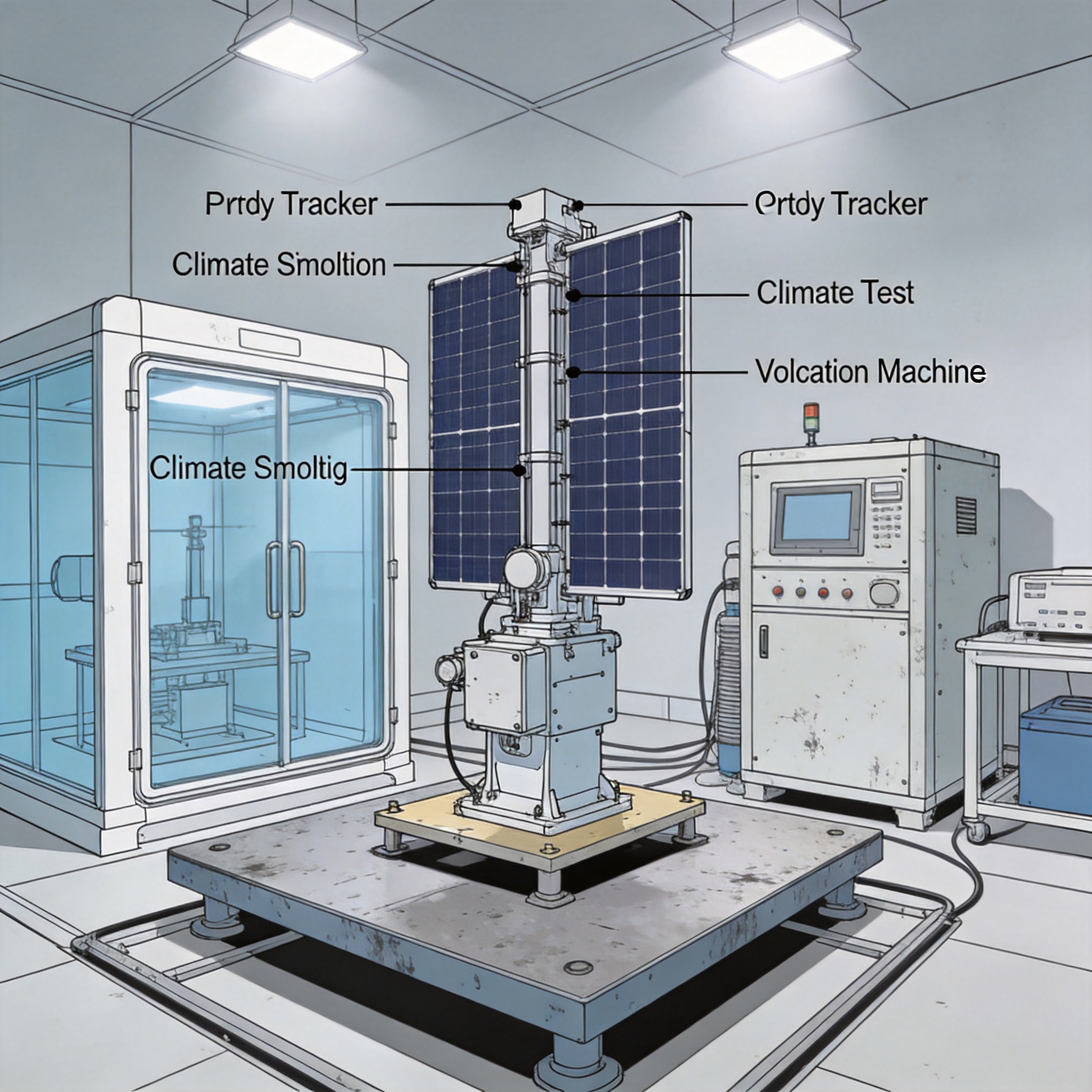
To verify a 20-year lifespan, we rely on accelerated aging tests that attack the weakest points: bearings, actuators, and coating systems. The most common test is **ASTM B117** for salt spray corrosion. For coastal installations, we typically require a minimum of 1,000 hours of salt spray exposure without red rust on critical structural components.
For the electronics and actuators, **UV testing** per ISO 4892-3 is essential. We expose cable insulation and polymer bushings to 2,500 hours of UV radiation to simulate 20 years of sunlight. Thermal cycling tests, often between -40°C and +85°C, check for solder joint fatigue and seal integrity. In one case, we found that a specific linear actuator failed after 8,000 thermal cycles due to grease degradation, a failure point not covered by the standard IEC test.
Here is a quick breakdown of the tests we use for a 20-year verification plan:
– **Salt Spray (ASTM B117):** 1,000+ hours for coastal rating.
– **UV Exposure (ISO 4892-3):** 2,500+ hours for polymer degradation.
– **Thermal Cycling:** 200 cycles from -40°C to +85°C for electronics.
– **Damp Heat (IEC 60068-2-78):** 1,000 hours at 85°C/85% RH for control boxes.
Field Verification: Real-World Data vs. Laboratory Results
Laboratory tests are necessary, but they cannot fully replicate the chaos of a real site. The most credible reliability verification comes from **field data correlation**. In our projects, we install strain gauges and inclinometers on prototype trackers to measure actual wind loads and vibration frequencies. This data is then compared to our laboratory simulations to validate the fatigue models.
For example, a project in a high-wind region of Texas showed that the actual gust factor was 15% higher than the IEC standard assumed. Without field verification, the slew drive would have been undersized. We now recommend a **12-month minimum field trial** for any new tracker design before mass production, specifically to monitor the “jitter” frequency caused by turbulent wind. This is particularly critical when comparing a linked system like the PV linked horizontal single-axis tracker solar mounting system, where the mechanical coupling between rows can introduce additional dynamic loads not present in independent tracker designs.
The key metric here is the **Damage Equivalent Load (DEL)** . We calculate the DEL from field strain data and compare it to the laboratory test cycles. If the field DEL is higher than the test DEL, the 20-year prediction is invalidated. This methodology aligns with the guidelines from the National Renewable Energy Laboratory (NREL) on wind load validation.
Common Failure Modes and How Tests Miss Them
Even with rigorous testing, certain failure modes remain elusive in the lab. The most common is **fretting corrosion** in the slew drive gear teeth. This occurs during micro-oscillations in high wind, slowly grinding the gear surface into dust. Standard load tests do not simulate this high-frequency, low-amplitude motion sufficiently.
Another missed failure is **cable management fatigue**. The torsion cables that carry power between the moving array and the stationary pedestal undergo complex bending. We have seen cables fail in year 5 because the test standard only required 10,000 flexes, while the actual site required 50,000 due to backtracking algorithms. To counter this, we now use a specific cable test rig that mimics the exact torsion angle of the tracker.
Finally, the **controller electronics** often fail due to voltage spikes from the drive motors, not from ambient temperature. To verify 20-year reliability, we perform a “brown-out” test simulating 100,000 power cycles. This has proven more effective than standard thermal testing in predicting control box failures. For sites considering a hybrid approach, the durability of the tracker’s drive system should be weighed against the simplicity of a fixed adjustable PV mounting structure with a 5-60 degree tilt, which eliminates moving parts entirely and thus bypasses many of these failure modes.





 English
 Español
 Deutsch
 Português
 Français
 Italiano