




Pourquoi c'est difficile
The array on a treatment works sits inside a functioning process plant, so the design question is less about solar engineering than about where the solar can physically go without disturbing the process.
- The most open land on a treatment works is usually crossed by underground process pipework, making foundation positioning the primary constraint
- Hydrogen sulphide and the humid environment around primary treatment are aggressive to steel and to coatings, and exposure varies sharply across the site
- Tanks, clarifiers and channels occupy the largest surfaces, so the useful array area is elevated rather than on the ground
- Continuous operation means no shutdown window, so all installation has to be non-intrusive and staged
- Chemical storage and dosing areas impose additional corrosion and segregation requirements that constrain layout
- Maintenance access for process equipment must remain unimpeded, which often determines array boundaries more than solar considerations do
Exigences d'ingénierie
These are the design inputs that decide whether a treatment works array can be built and maintained without interfering with the process.
- Process pipework and service mapping across the array footprint, with foundation positions cleared against every buried route
- Corrosion class assessed per zone, recognising that hydrogen sulphide exposure varies across a treatment works rather than being uniform
- Foundation methods that avoid excavation where process pipework is dense, and avoid vibration near sensitive structures
- Elevated or surface-mounted structure design where tanks, clarifiers or channels are used, with load and access provisions agreed with the process operator
- Layout boundaries set by process maintenance access rather than by array geometry
- Materials and detailing resistant to sulphide exposure, including fastener specification and joint sealing
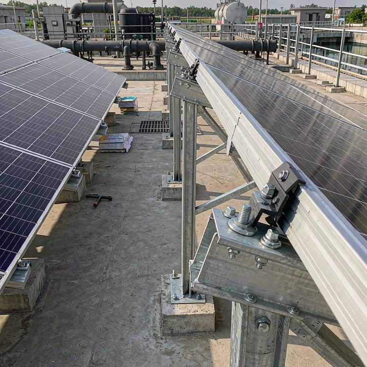
Selection guidance: map the process pipework before laying out the array. On treatment works, the underground network constrains more of the layout than the surface area does.
Comment nous résolvons le problème
- Foundation positioning driven by a surveyed pipework map, with screw piles or ballasted bases where excavation near process pipes is not acceptable
- Corrosion specification varied by zone across the site, so the sulphide-exposed areas receive heavier protection while clean areas do not carry unnecessary cost
- Surface-mounted structures over channels and tanks where ground area is unavailable, designed for the loads and access requirements of the specific structure
- Layout boundaries aligned to process maintenance access routes, so no array blocks equipment or pipework access
- Non-intrusive installation methods and staged delivery, since treatment works operate continuously
- Fastener and joint detailing suited to humid sulphide exposure, including isolation at dissimilar metal interfaces
Au-delà de la structure
- Coordination with the site’s electrical infrastructure, using existing cable corridors and substation capacity where available
- Provisions for future process expansion clearly marked, so later works do not conflict with the array footprint
Points de référence
Les projets de référence ci-dessous, de type et d'envergure comparables et documentés publiquement, sont cités à titre d'illustration des pratiques d'ingénierie. Ils ne constituent pas un historique de réalisations.
- Wastewater treatment works in Northern Europe where hydrogen sulphide exposure drove zone-specific coating specifications.
- Water utility solar programmes in the United States where more than a fifth of utilities were operating or planning solar installations by 2030, largely on their own treatment sites.
- Treatment plant arrays in South-East Asia where dense process pipework forced screw pile foundations across much of the usable area.
Normes et conformité
- ASCE 7 / EN 1991 / AS-NZS 1170 wind load cases with site-specific terrain categories
- IEC 62727 tracker structural requirements where tracking structures are in scope
- EN 1090-2 or AISC 360 fabrication and execution class documentation
- ISO 1461 hot-dip galvanizing, ISO 9223 corrosivity classification driving zinc mass
- ISO 9001:2015 quality system, ISO 14001 environmental management on request
- Third-party aeroelastic wind tunnel study available for large-format modules
Assurance qualité
Every batch ships with mill certificates, coating-thickness logs and bolt records; welds follow EN 1090 or AISC execution classes. Structure warranty runs to 10 years against a 25-30 year service design life, and spare-part packages are documented so year-12 repairs do not depend on year-1 memory.
Documents que vous recevez
La documentation est conçue pour les audits, et non pour la décoration : notes de calcul de structure indiquant les cas de charge et les normes utilisées ; base de conception des fondations alignée sur votre rapport géotechnique ; certificats de matériaux pour l’acier et la visserie ; certificats de galvanisation avec l’épaisseur de revêtement mesurée par lot ; plans d’assemblage avec tableaux de couples de serrage ; et documentation d’emballage correspondant aux manifestes des conteneurs. Pour les projets financés, nous ajoutons des déclarations de conformité au format des organismes prêteurs ; pour les appels d’offres publics, nous répondons aux cahiers des charges documentaires point par point.
Planification de la durée de vie et de la maintenance
La planification du remplacement fait partie intégrante de la conception : la géométrie des fixations permet le remplacement individuel des modules sans découpe des rails, les têtes de pieux peuvent être rénivelées après tassement et les kits de pièces de rechange sont dimensionnés en fonction de votre classe environnementale et de votre capacité. Ainsi, les travaux de remise en état en milieu de vie sont rapides, prévisibles et indépendants du catalogue de produits du fournisseur d'origine.
Considérations relatives aux coûts et au commerce
- Screw or ballasted foundations add 15-30 percent over driven piles and are usually the only option where process pipework is dense
- Zone-specific coating specification avoids over-specifying the whole site, which is worth 10-30 percent of the corrosion budget
- Elevated structures over tanks cost substantially more per kilowatt than ground-mount, and are justified by land availability rather than economics
- Continuous-operation installation adds 10-20 percent to labour, because work is staged around process constraints
- Lead time: 4-9 weeks depending on foundation method and coating specification
Foire aux questions
Can solar be installed over tanks and clarifiers?
How does hydrogen sulphide affect the structure?
What foundation can we use where pipework is dense?
Do we need to shut down treatment to install?
Can the array help with peak demand charges?
Guides et pages d'application associés
Poursuivez avec les pages les plus proches de votre type de projet.
- Industrial Ground-Mount & Captive Power – Aperçu du groupe pour cette gamme
- Ground-Mount Racking for Industrial Captive Power
- Solar Racking for Steel, Cement & Heavy Industry Sites
- Brownfield, Reclaimed & Post-Mining Solar Projects
- Wastewater Treatment Plant Solar Projects
- Agrivoltaic & Dual-Use Cropland Projects
Ce que nous devons citer
- Site plan with process pipework, tanks, clarifiers and maintenance access routes
- Any hydrogen sulphide or chemical exposure data, or access to the site for assessment
- Available land area and any structures considered for surface-mounted arrays
- The site’s electrical load profile and existing connection capacity
Parlez à un ingénieur en structure
Send your site plan and process layout, and we will return an array layout, foundation options and a zone-specific corrosion specification.
 English
 Español
 Deutsch
 Português
 Français
 Italiano