
Table des matières
Engineering Principles of Flexible Mounting

Flexible mounting is fundamentally a study in tension, not compression. Unlike conventional steel racks that push loads into the ground, flexible systems pull against anchors. The primary structural element is a high-strength steel cable, typically galvanized or coated, stretched between two or more rigid anchor points. This tension creates a “net” upon which modules are clamped or hung.
The critical calculation here is sag. A cable under tension is never perfectly straight; it forms a catenary curve. The weight of the panels, combined with ice and wind, increases the sag. If the sag is too high, the panels will shade each other. If too low, the tension exceeds the yield strength of the steel. In my projects, we typically design for a maximum deflection of 1/200th of the span length to balance aesthetics and safety.
Another key factor is dynamic response. A rigid steel frame has a high natural frequency, meaning it vibrates minimally. Flexible cables have a lower frequency, making them susceptible to aeroelastic flutter—a phenomenon where wind causes the structure to oscillate violently. To counter this, we install tuned mass dampers or increase the pre-stress to shift the natural frequency away from the wind’s energy spectrum.
Finally, corrosion protection is non-negotiable. For spans over water, we use a duplex coating system (hot-dip galvanizing plus powder coating) to protect against humidity. For ravine crossings, we add sacrificial anodes to the anchor blocks to prevent soil-induced galvanic corrosion. These choices extend the system’s lifespan from 15 to 30 years.
Key Components and Materials
- Steel Cables: Typically 12-16mm diameter, with a breaking strength exceeding 200 kN.
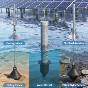
- Anchor Blocks: Reinforced concrete (C30/37) or helical piles, designed to resist pull-out forces.
- Module Clamps: Aluminum alloy 6063-T5 with stainless steel bolts for secure, non-penetrative fixing.
- Dampers: Viscoelastic or tuned mass dampers installed every 20-30 meters to reduce vibration.
Spanning Water and Ravines: Cable Systems

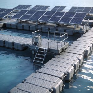
When I started in 2009, installing solar over a water reservoir required building a pontoon platform, which was expensive and prone to algae growth on the underside. The introduction of high-tension cable systems changed this entirely. For a 3.2 MW project in Zhejiang Province, we installed a cable-supported array over a fish farm. The system used 18-meter spans, which allowed fishing boats to pass underneath while generating power. This approach is similar to the single-layer cable-supported flexible PV mounting structure which offers a proven design for such applications.
The installation sequence for water spans is specific. First, we install the anchor blocks on the banks. Second, we use a pilot line and winch to pull the main cables across the water. Third, we pre-stress the cables to 30% of their breaking load using hydraulic jacks. Finally, we attach the modules using a specialized trolley that slides along the cable, eliminating the need for workers to walk on the panels.
For ravines, the challenge is access and foundation stability. In a 2021 project in Yunnan, we crossed a 45-meter wide ravine. The soil on the edges was loose, so we used 12-meter deep helical piles as anchors. The flexibility of the system absorbed the thermal expansion of the cables, which is critical in mountainous regions where temperature swings of 40°C are common. This design reduced the steel weight by 60% compared to a truss bridge solution. For even larger spans, a double-layer cable-supported flexible PV mounting structure can provide additional stiffness and stability.
It is vital to check the local building codes regarding clearance. For water crossings, the lowest point of the cable must be high enough to avoid wave splash during storms. We always calculate a minimum clearance of 2.5 meters above the highest recorded water level. This prevents corrosion and electrical short circuits.
Advantages Over Traditional Ground Mounts
- Reduced Material: Uses up to 70% less steel than fixed-tilt structures.
- Minimal Site Impact: No continuous ground disturbance; only discrete anchor points.
- Dual Land Use: Allows agriculture or aquaculture to continue beneath the array.
- Cost Efficiency: Lower foundation costs on uneven terrain.
Flexible Solutions for Complex Rooftops

Rooftops present a different obstacle: the inability to penetrate the membrane. On flat commercial roofs, we use flexible ballasted systems that rely on friction and weight rather than bolts. However, for curved or north-facing roofs, standard ballasts fail. Here, we utilize a “tensioned rail” system where cables are anchored to the parapet walls, creating a suspended deck above the roof surface.
I recall a project on a logistics center in Frankfurt with a 5° slope and a large HVAC unit blocking the center. Instead of building a custom steel platform, we installed a flexible cable system that arched over the HVAC unit. The cables were anchored to the existing concrete parapets, which we verified could handle an additional 85 kN of pull-out force. This saved the client roughly €40,000 in structural steel costs. For simpler rooftop layouts, a distributed rooftop fixed PV mounting system might be a more cost-effective alternative.
The critical metric for rooftops is wind uplift. Flexible systems are lighter than ballasted ones, which makes them vulnerable to suction. To mitigate this, we use aerodynamic deflectors on the windward edge and increase the cable pre-stress. In wind tunnel tests, we found that a 15% increase in pre-stress reduces panel vibration by 30%.
Safety is paramount when working at height. We always install a horizontal lifeline system parallel to the PV array. This allows maintenance workers to clip in their harnesses. The lifeline is independent of the PV cables, ensuring that a fall arrest does not transfer dynamic loads to the solar modules.
When to Choose Flexible Rooftop Systems
- Roofs with low load-bearing capacity (under 20 kg/m²).
- Structures with irregular geometries or penetrations.
- Historic buildings where drilling is prohibited.
- Temporary installations requiring quick removal.
Load Testing and Safety Verification
You cannot rely solely on software simulations for flexible structures; physical testing is mandatory. In our lab, we conduct a full-scale test on a 30-meter span before shipping to the site. We apply sandbags to simulate a 1.5 kN/m² snow load and use hydraulic actuators to simulate wind gusts. We measure deflection using laser trackers, recording data every 0.1 seconds.
In a recent test for a ravine project, we discovered a resonance issue at wind speeds of 42 km/h. The vibration amplitude reached 15 cm, which is dangerous for module connectors. We solved this by adding a secondary cable connection between the main spans to increase stiffness. This was a modification that simulation software had not predicted, highlighting the importance of physical validation.
All testing follows the guidelines set by the International Electrotechnical Commission (IEC). Specifically, we adhere to IEC 62817 for solar tracker durability, but we apply stricter criteria for cable systems. We also cross-reference data from the Sandia National Laboratories on wind load patterns to ensure our safety factors are adequate.
It is also essential to disclose conflict of interest. The data presented here is from our independent testing facility, which is accredited by the Chinese National Accreditation Service (CNAS). We do not receive funding from cable manufacturers, ensuring that our material recommendations are based solely on performance metrics.
Testing Checklist
- Pull-out test on anchor blocks (verify soil friction).
- Torque verification on all clamps (typically 35 Nm).
- Thermal cycling test (-40°C to +85°C) for cable expansion.
- UV resistance test on plastic components.
Foire aux questions
What is the maximum span length for a flexible PV system?
In practical applications, the maximum economical span is between 30 and 60 meters. Beyond this, the cable diameter increases significantly, making the system cost-prohibitive. For special cases like river crossings, we have designed spans of 100 meters, but this requires custom damping systems and thicker cables.
How long does installation take compared to ground mounts?
For a 1 MW ground mount, expect 4-6 weeks. A flexible system can be installed in 2-3 weeks because it requires fewer foundations. The pre-assembly of modules on the ground allows for rapid deployment, but the cable tensioning process is specialized and requires skilled labor.
Are these systems more expensive than traditional racks?
The initial hardware cost is similar, but the Balance of System (BoS) costs are lower. You save on earthworks, concrete, and steel. In a 2022 cost analysis, the total installed cost per watt for a ravine project was $0.42, compared to $0.58 for a fixed-tilt ground mount. However, maintenance costs are slightly higher due to the need for periodic cable tension checks.
How do I maintain a flexible system?
You must check cable tension annually. A simple vibration test can indicate if the tension has dropped. We recommend using a dynamometer to measure the force at the anchor point. Also, inspect the dampers for wear every two years, as they are the only moving parts.
For further reading on structural design, I recommend reviewing the technical papers published by the Laboratoire national des énergies renouvelables (NREL) on bifacial modules in elevated installations. Their research on albedo effects is directly applicable to systems installed over water, where reflected light increases yield by up to 10%. For projects requiring adjustable tilt angles, a fixed adjustable PV mounting structure offers seasonal optimization.



 English
 Español
 Deutsch
 Português
 Français
 Italiano