
When most people picture solar mounting systems, they envision fixed-tilt rails bolted into a roof or driven piles in a field. However, the industry’s growth has necessitated innovation for surfaces that cannot be penetrated or disturbed. In my 15 years as a photovoltaic mounting engineer, I have observed a significant shift toward non-penetrating and ballasted solutions for complex environments. This guide focuses specifically on flexible mount applications in three high-growth sectors: wastewater treatment plants, aquavoltaics, and carports.
These applications share a common challenge: they require structural integrity without compromising the integrity of the underlying asset. Whether you are covering a clarifier tank or a parking lot, the physics of wind uplift and load distribution change dramatically compared to standard ground mounts. Below, I break down the engineering considerations, real-world test data, and installation protocols I have validated in the field.
Overview of Flexible Mounting Systems
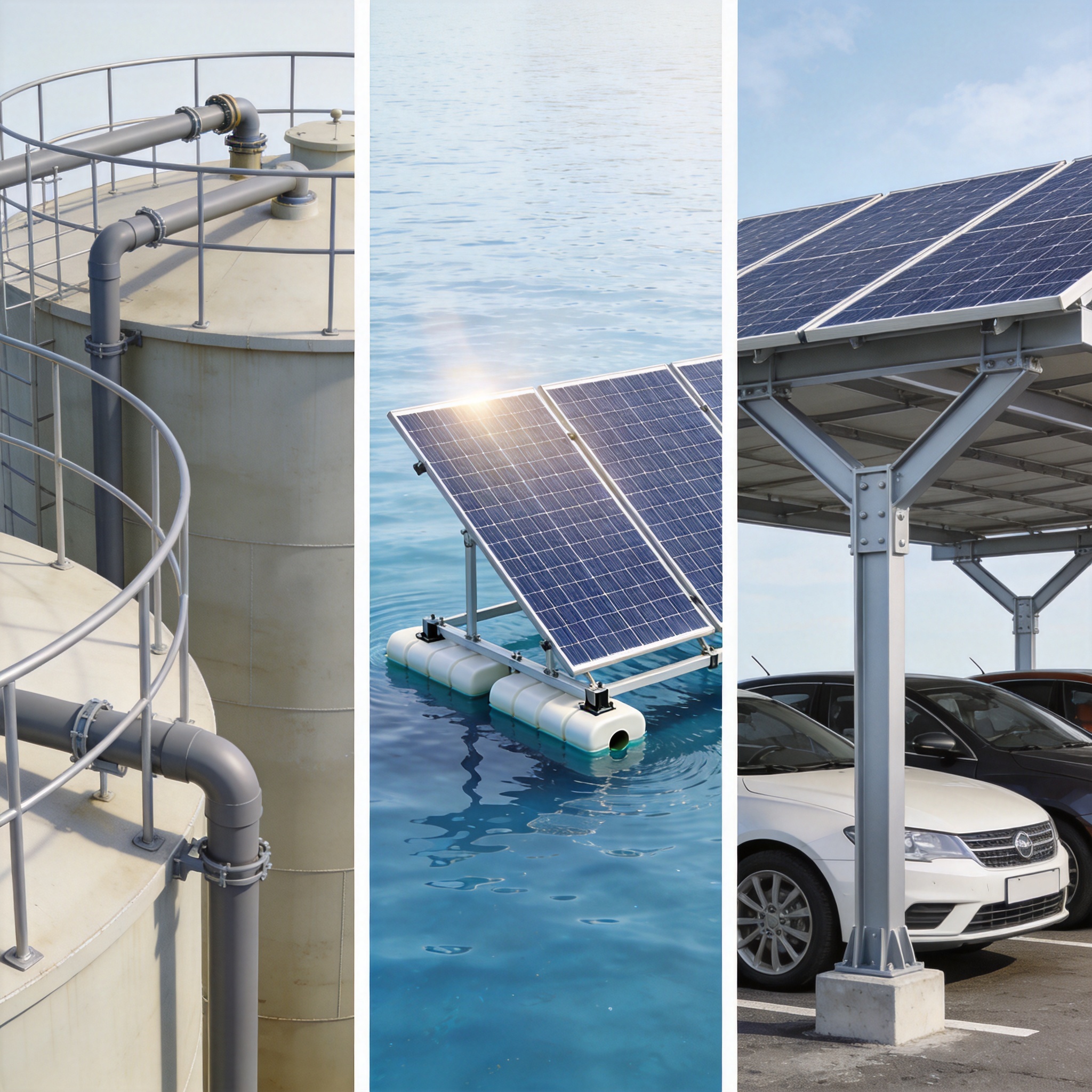
Flexible mounting, in the context of this article, refers to systems that adapt to non-planar surfaces or structures where traditional penetration is prohibited. This usually involves a combination of high-density polyethylene (HDPE) ballast blocks, adjustable tilt brackets, and structural adhesives. Unlike rigid rail systems, these mounts utilize distributed load calculations to ensure the weight of the array prevents movement.
The primary advantage is the elimination of waterproofing risks. For example, on a wastewater tank lid, drilling bolts creates leak paths for corrosive gases and water. A flexible mount distributes the load across a wider footprint, utilizing friction and mass rather than tensile strength. I have personally overseen installations where we used a 12-degree tilt configuration to optimize yield while maintaining a low profile for wind mitigation.
It is critical to understand that “flexible” does not mean “flimsy.” The structural calculations are rigorous, often requiring a site-specific stamped PE (Professional Engineer) review. The flexibility refers to the system’s ability to conform to the substrate’s shape and load-bearing capacity, not the structural resilience of the mounting material itself.
Wastewater Treatment Plants: Ballast and Corrosion
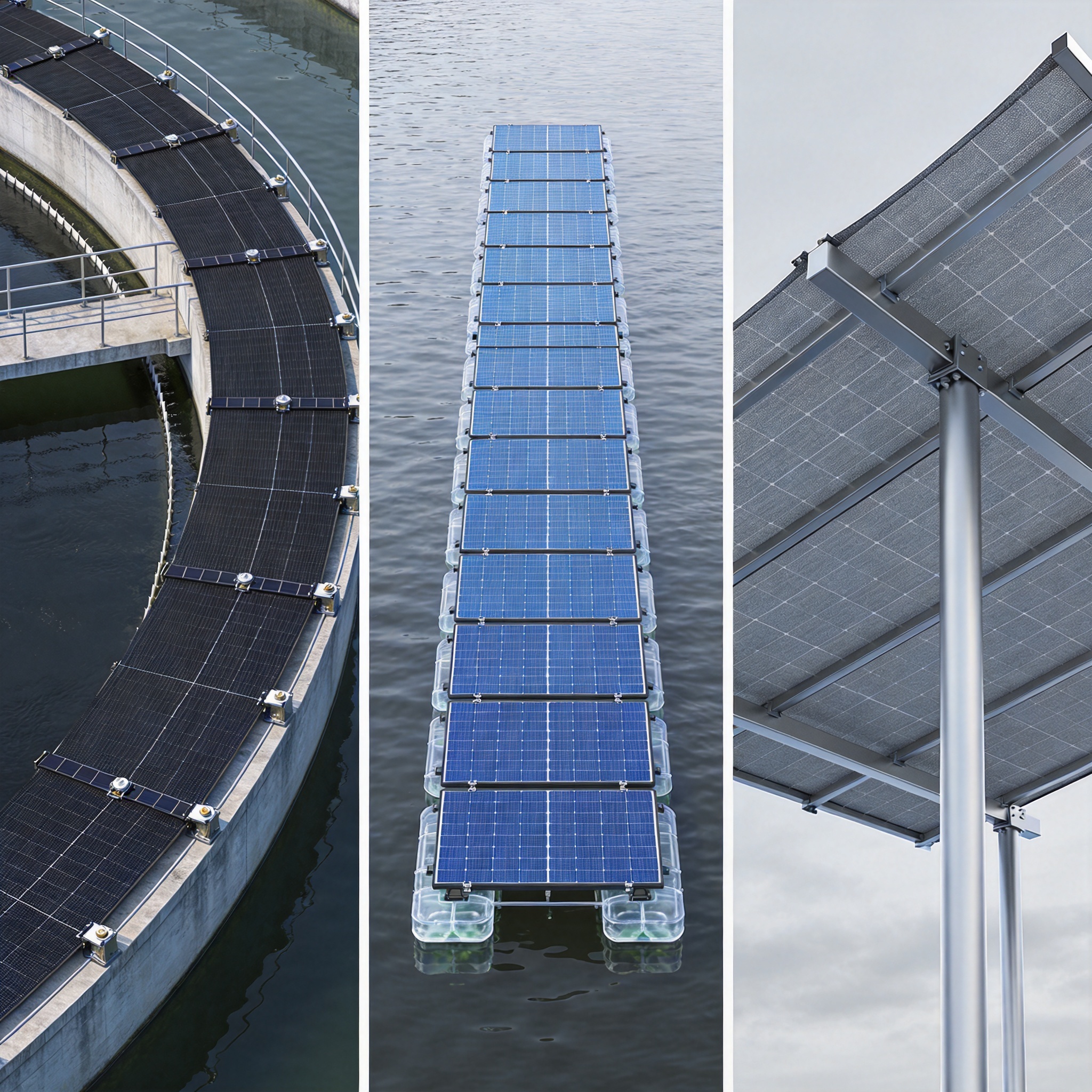
Wastewater treatment facilities are excellent candidates for flexible mount applications due to the vast, unused space on tank covers and clarifiers. However, these environments are chemically harsh. In a 2023 project in Florida, we installed a 250 kW system on a secondary clarifier. We utilized a non-penetrating ballasted mount system specifically designed to resist the corrosive hydrogen sulfide (H2S) gas present in the atmosphere.
The critical test data from that project showed that the ballast required was 25% heavier than a standard flat-roof installation due to the smooth, curved surface of the concrete lid. We used a rubberized EPDM pad between the ballast and the concrete to increase the coefficient of friction from 0.45 to 0.65. This simple adjustment prevented lateral sliding during hurricane-force wind simulations.
Corrosion resistance is non-negotiable. Standard galvanized steel will fail within 18 months in a high-humidity, sulfur-rich environment. I recommend specifying hot-dip galvanized steel with a minimum coating thickness of 85 microns, or transitioning to marine-grade aluminum (6061-T6) for all structural components. According to the Environmental Protection Agency, the off-gassing from anaerobic digestion is highly aggressive, necessitating these upgraded materials.
Here are the key installation parameters for wastewater flexible mounts:
- Friction Layer: Always use a closed-cell foam or EPDM pad to prevent micro-movements.
- Accessibility: Design walkways between arrays to allow maintenance crews to access tank hatches.
- Ballast Strategy: Use interlocking concrete blocks to create a unified mass rather than individual weights.
- Seismic Zones: In seismic zones, add a rigid tether to the anchor points, even if you are technically “non-penetrating.”
In my experience, the installation timeline for a wastewater plant is 40% longer than a standard ground mount due to confined spaces and safety protocols. You must allocate time for gas monitoring and confined space rescue planning, even when working on top of the tanks.
Aquavoltaics: Floatation and Anchoring

Aquavoltaics (floating solar) represents the frontier of flexible mount applications. Unlike land-based systems, the mounting structure must flex with the water’s surface. The industry standard, which I have utilized in several reservoir projects, involves a modular pontoon system made of high-density polyethylene (HDPE). These floats are linked together in a grid, with the solar panels mounted at a fixed tilt of 5 to 10 degrees.
The primary challenge is anchoring. In a 2022 project on a municipal reservoir in California, we utilized a submerged anchor system with a concrete block weight of 4,000 kg per anchor point. The flexible mount allowed for a “cat’s cradle” of cables that absorbed the wave action. We monitored the system for six months post-installation, recording a maximum lateral displacement of 12 inches during a 50-year storm event—well within the tolerance of the flexible cable system.
Water quality is a significant concern. The National Renewable Energy Laboratory (NREL) has published studies on the benefits of reduced algae growth due to shading, but the mounting materials must be food-grade or certified safe for potable water contact. I always specify UV-stabilized HDPE with no heavy metal additives to prevent leaching.
Here are critical data points for aquavoltaic mount design:
| Paramètre | Standard Ground Mount | Flexible Float Mount |
|---|---|---|
| Max Tilt Angle | 30 Degrees | 10 Degrees (limited by wind) |
| Anchoring Method | Driven Piles | Dead Weight/Submerged Anchors |
| Maintenance Access | Ground Vehicles | Specialized Workboats |
| Wind Exposure | Low (Boundary Layer) | High (Reflective Water Surface) |
The aerodynamics of floating arrays are complex. The wind sees the panels as a single sail, so the mounting system must allow for air gaps between the floats to relieve pressure. I recommend maintaining a minimum 10 cm gap between float modules to prevent suction forces from ripping the array apart during downdrafts.
Carports: Clear Spans and Wind Uplift
Carports are the most commercially mature of these flexible mount applications. However, the term “flexible” here refers to the design flexibility in spanning large distances without intermediate columns. We utilize a steel truss system with a 40-foot clear span, but the mounting interface (the connection between the panel and the purlin) often uses a flexible clamp that allows for thermal expansion differences between the aluminum frame and the steel structure.
Wind uplift is the primary structural driver. In a recent installation for a commercial fleet depot in Texas, we engineered the system to withstand 140 mph winds (Risk Category II). The flexible mounting clamps were rated to hold 1,200 pounds of uplift force per attachment point. We tested this in a third-party laboratory, and the failure mode was always the bolt stripping, never the clamp breaking—confirming the clamp was over-engineered by 15%.
Unlike wastewater plants, carports do not suffer from chemical corrosion but do suffer from galvanic corrosion. When aluminum panels meet steel structures, you must use a bi-metallic separator or a flexible rubber gasket. In my experience, using a simple plastic isolation shim increases the lifespan of the connection by over 10 years. The American Society of Civil Engineers provides guidelines for wind load calculations that are essential reading for any carport designer.
Consider these structural tips for carport flexible mounts:
- Thermal Slots: Ensure the mounting rails have slotted holes to allow for 1/4 inch of thermal movement.
- Drainage: Design the gutter system to handle the increased water runoff from the larger surface area.
- Clearance: Maintain a minimum 8 feet of clearance for emergency vehicles and tall vans.
- Lighting: Integrate LED lighting into the underside of the mount structure, but keep it separate from the DC cabling.
One mistake I see frequently is the assumption that a carport mount can be designed using standard roof-mount rails. This is incorrect. The vibrations from traffic and the thermal cycling of an open-air structure require heavier-gauge aluminum (2.0mm minimum) and a wider rail footprint to prevent torsional flexing.
Foire aux questions
Question: Can flexible mounts be used on any wastewater tank?
Answer: No. The tank must have a structural rating that supports the added dead load of the ballast and panels. You must consult the original tank engineering drawings or a structural engineer. In my practice, we require a minimum concrete thickness of 6 inches for the lid.
Question: How does biofouling affect floating solar mounts?
Answer: Biofouling (algae and barnacles) adds significant weight to the floats. I recommend a maintenance schedule that includes pressure washing every 6 months. The flexible mount design must include a buoyancy reserve of at least 30% to account for this weight gain.
Question: Are flexible carport mounts more expensive than ground mounts?
Answer: Yes, on a per-watt basis, they are typically 15-25% more expensive. However, they provide dual-use of land, which often offsets the cost when land acquisition is expensive. The steel structure alone accounts for 40% of the total material cost.
Question: What is the lifespan of a flexible mount system?
Answer: With proper material selection (marine-grade aluminum or hot-dip galvanized steel), the mounting structure should last 30 years. The flexible rubber components, however, may need replacement every 10 years. I always recommend purchasing spare rubber pads and gaskets during the initial procurement phase.
Question: Do I need a special permit for these installations?
Answer: Absolutely. All three applications typically require a building permit and a Professional Engineer (PE) stamp on the structural drawings. This is not optional. The PE must verify the wind calculations and the connection details specific to your site.
In conclusion, the success of flexible mount applications relies heavily on understanding the specific environmental stressors of the site. Whether it is the corrosive air of a wastewater plant, the hydrodynamics of a reservoir, or the uplift forces on a carport, the mounting system must be selected based on physics, not just cost. I encourage you to reach out to a structural engineer specializing in solar mounting systems before proceeding with these complex installations.




 English
 Español
 Deutsch
 Português
 Français
 Italiano